29
Schiller Grounds Care, Inc. P/N 802-0006
APPENDIX B RELATED DOCUMENTATION
1 2 3
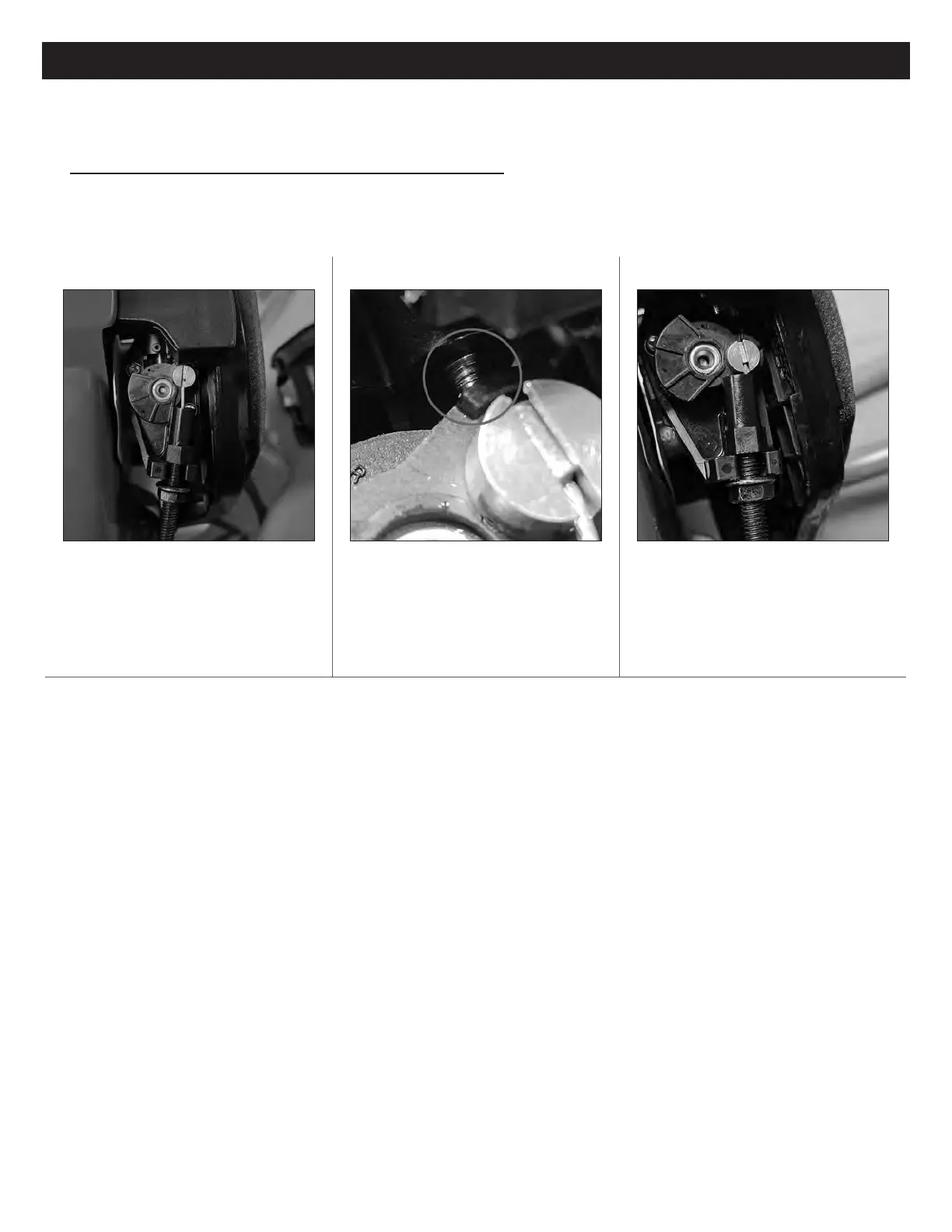
Remove the air cleaner cover to expose the
throttle connections. A disengaged throttle
looks like the above image with the throttle
cable exposed.
Disengaged throttle position – rm against top
screw
Depress the throttle trigger to see the throttle
lever travel to the engaged position (above).
Adjust the lower, metal nut as needed before
nal tightening. NOTE: Final tightening with a
wrench should only be performed on the metal
nut.
VISUAL CHECK FOR THROTTLE
ASSEMBLY XP TILLER
During the initial assembly of a new machine, it is important to visually check the throttle connection before running the machine for
the rst time.