Y1 and Y2 = Safety outputs → Safety monitoring module
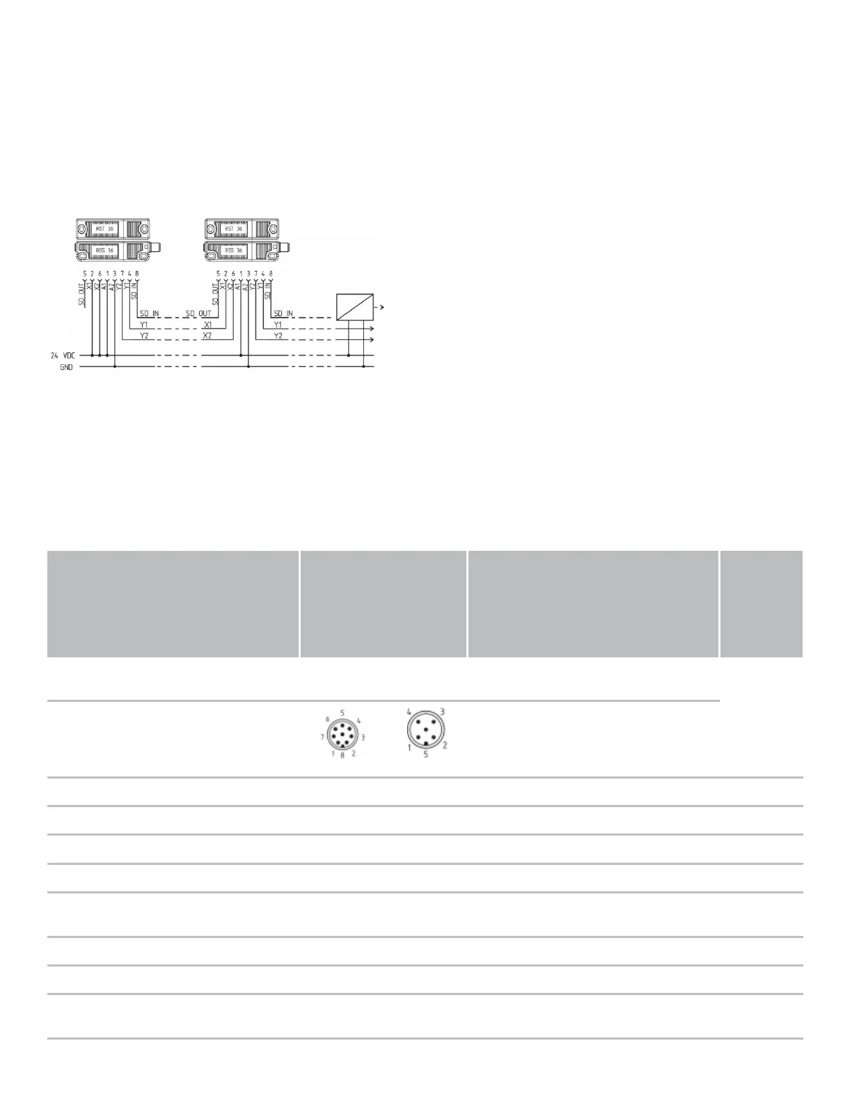
Wiring example 2: series-wiring of the RSS 36 with serial diagnostic function
In devices with the serial diagnostics function (ordering suffix -SD), the serial diagnostics connections are wired in
series and connected to a SD-Gateway for evaluation purposes. The voltage is supplied to both safety inputs of the last
safety sensor of the chain (considered from the safety-monitoring module).
The safety outputs of the first safety sensor are wired to the safety-monitoring module. The serial Diagnostic Gateway
is connected to the serial diagnostic input of the first safety sensor.
Y1 and Y2 = Safety outputs → Safety monitoring module
SD-IN → Gateway → Field bus
5.4 Wiring configuration and connector accessories
Function safety switchgear Pin configuration of the
connector
Colour codes of the Schmersal
connectors
Poss.
colour
codes of
other
customary
connectors
8-pin
version ST
5-pin
version ST
8-pin version ST 5-pin
version ST
to IEC
60947-5-2:
2007
with
conventiona
l diagnostic
outpu
with serial
diagnostic
function
IP67 / IP69
(PUR)
IP69 (PVC) IP67 / IP69
(PUR)
A1 Ue 1 1 WH BN BN BN
X1 Safety input 1 2 BN WH WH
A2 GND 3 3 GN BU BU BU
Y1 Safety output 1 4 4 YE BK BK BK
OUT Diagnoseaus
gang
SD-output 5 5 GY GY GY GY
X2 Safety input 2 6 PK VT PK
Y2 Safety output 2 7 2 BU RD WH VT
IN without
function
SD-input 8 RD PK OR