7 Working principle and diagnostic function
7.1 Mode of operation of the safety outputs
The safety outputs can be integrated into the safety circuit of the control system.
The opening of a safety guard, i.e. the actuator is removed out of the active zone of the sensor, will immediately
disable the safety outputs of the sensor.
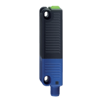
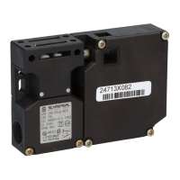
7.2 Diagnostic-LEDs
The safety sensor indicates the operating condition and faults by means of three-colour LEDs located in the lateral
surfaces of the sensor.
F
The following LED indicators are the same for safety sensors with conventional diagnostic output as for those with a serial
diagnostic function.
The green LED indicates that the safety sensor is ready for operation. The supply voltage is on and all safety inputs are
present.
Flashing (1Hz) of the green LED signals that a voltage is missing on one or both of the safety inputs (X1 and/or X2).
The yellow LED always signals the presence of an actuator within range. If the actuator is operating in the limit area of
the sensor switching distance, it will be indicated by flashing.
The flashing can be used to prematurely detect variations in the clearance between the sensor and the actuator (e.g.
sagging of a safety guard). The sensor must be adjusted before the distance to the actuator increases and before the
safety outputs are disabled, thus stopping the machine. If an error is detected, the red LED will be activated.
LED indication (red) Error cause
1 flash pulse Error output Y1
2 flash pulses Error output Y2
3 flash pulses Cross-wire Y1/Y2
4 flash pulses ambient temperature too high
5 flash pulses Wrong or defective actuator
Continuous red Internal fault, with yellow flashing teaching
procedure
7.3 Operating principle of the electronic diagnostic output
A diagnostic output additionally indicates the switching condition of the safety switchgear. These signals can be used in
a downstream control.
The short-circuit proof diagnostic output OUT can be used for central visualisation or control tasks, e.g. in a PLC.
The diagnostic output is not a safety-related output.