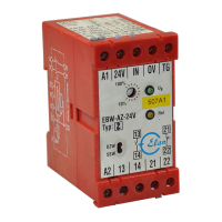
Table 3: Tabular overview of status signals, warnings or error messages(The described condition is reached, when Bit = 1)
Communication directions: Request byte: from the PLC to the local safety sensor
Response byte: from the local safety sensor to the PLC
Warning/error byte: from the local safety sensor to the PLC
Bit n° Request byte Response byte Diagnostic
Error warning Error messages
Bit 0: --- Safety output activated Error output Y1 Error output Y1
Bit 1: --- Actuator detected Error output Y2 Error output Y2
Bit 2: --- --- Cross-wire Y1/Y2 Cross-wire Y1/Y2
Bit 3: --- --- Temperature too high Temperature too high
Bit 4: --- Input condition X1 and X2 --- Incorrect or defective
actuator
Bit 5: --- Actuated in limit area Internal device error Internal device error
Bit 6: --- Error warning Communication error
between the field bus
Gateway and the safety
switchgear
---
Bit 7: Error reset Error
(enabling path switched
off)
--- ---
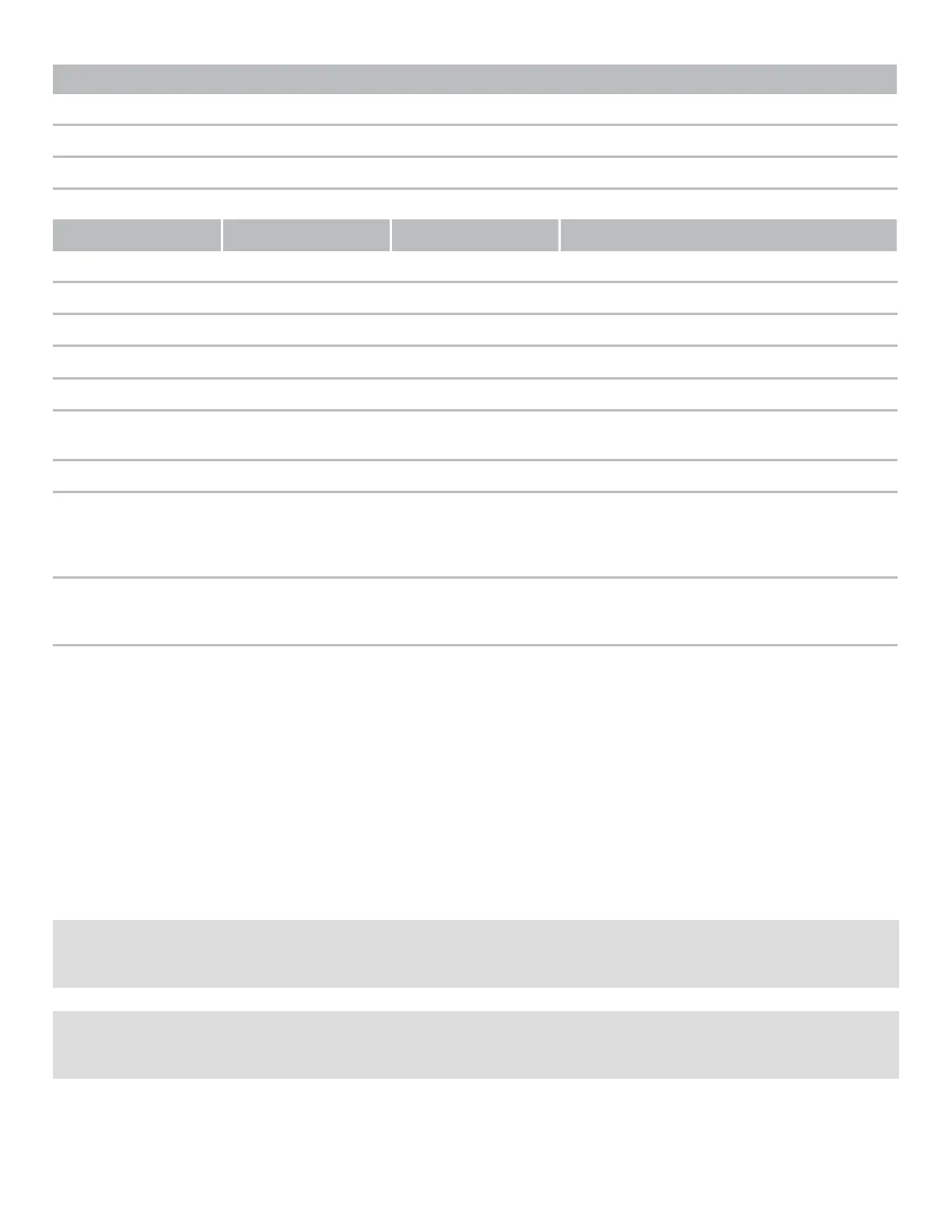
8 Set-up and maintenance
The safety function of the safety components must be tested. In the case of correct installation and adequate use, the
safety switchgear features maintenance-free functionality. A regular visual inspection and functional test, including the
following steps, is recommended:
1. Check fixation of the safety switch and the actuator.
2. Fitting and integrity of the cable connections.
3. The system is free of dirt and soiling (in particular metal chips).
2
Adequate measures must be taken to ensure protection against tampering either to prevent tampering of the safety guard, for
instance by means of replacement actuators.
2
Damaged or defective components must be replaced.