5
Montage- und Betriebsanleitung
für 2-Backen-Parallelgreifer Type PGN
Assembly and Operating Manual for
for 2-Finger-Parallel-Gripper Type PGN
3. Lieferumfang
– PGN (ohne Aufsatzbacken)
BEIPACK:
– 2 O-Ringe (Pos. 43) Ø 4 x 1.5
(PGN 50, 64 Ø 3 x 1 - PGN 380 Ø 5 x 1.5)
– 2 Zylinderstifte (Pos. 51)
–
Schaltnocken für Näherungsschalter (außer PGN 50, 200, 300)
– 3
Distanzplatten und entsprechende Befestigungsschrauben
(nur PGN 50)
– 2 Spannhülsen für Näherungsschalter Ø 12
(nur PGN 200 und 300)
ZUBEHÖR: (bei separater Bestellung, siehe Katalog)
– Induktive Näherungsschalter
– Flexibler Positionssensor
– Druckerhaltungsventil
– Adapterplatten
– Aufsatzbacken
4. Technische Daten
Die technischen Daten entnehmen Sie bitte dem aktuellen Katalog.
– Der von dem Greifer ausgehende Luftschall ist ≤ 70 dB (A)
5. Montage
ACHTUNG!
Bei der Montage des Greifers muss die Energiever-
sorgung abgeschaltet sein. Beachten Sie auch die
Sicherheitshinweise auf den Seiten 3 und 4.
Fixieren Sie den Greifer mit den beiden Fixierbohrungen an der
Grund- oder Seitenfläche (zwei Zylinderstifte im Beipack):
3. Scope of delivery
– PGN (without top jaws)
ENCLOSED PACK:
– 2 O-rings (Pos. 43) Ø 4 x 1.5
(PGN 50, 64 Ø 3 x 1 - PGN 380 Ø 5 x 1.5)
– 2 Dowel pins (Pos. 51)
– Control cam for proximity switches
(except PGN 50, 200 and 300)
– 3 washers and suitable fastening screws (only PGN 50)
– 2 clamping sleeves for proximity switches Ø 12
(only PGN 200 and 300)
ACCESSORIES: (on separate order, see catalog)
– Inductive proximity switches
– Multiple positioning sensor
– Double check safety valve
– Adaptor plates
– Top jaws
4. Technical Data
For technical data, please refer to the current catalogue.
– Air borne noise of the gripper is ≤ 70 dB (A)
5. Assembly
CAUTION!
The power supply must be removed before starting
assembly of the gripper. Please also consider the
safety instructions on page 3 and 4.
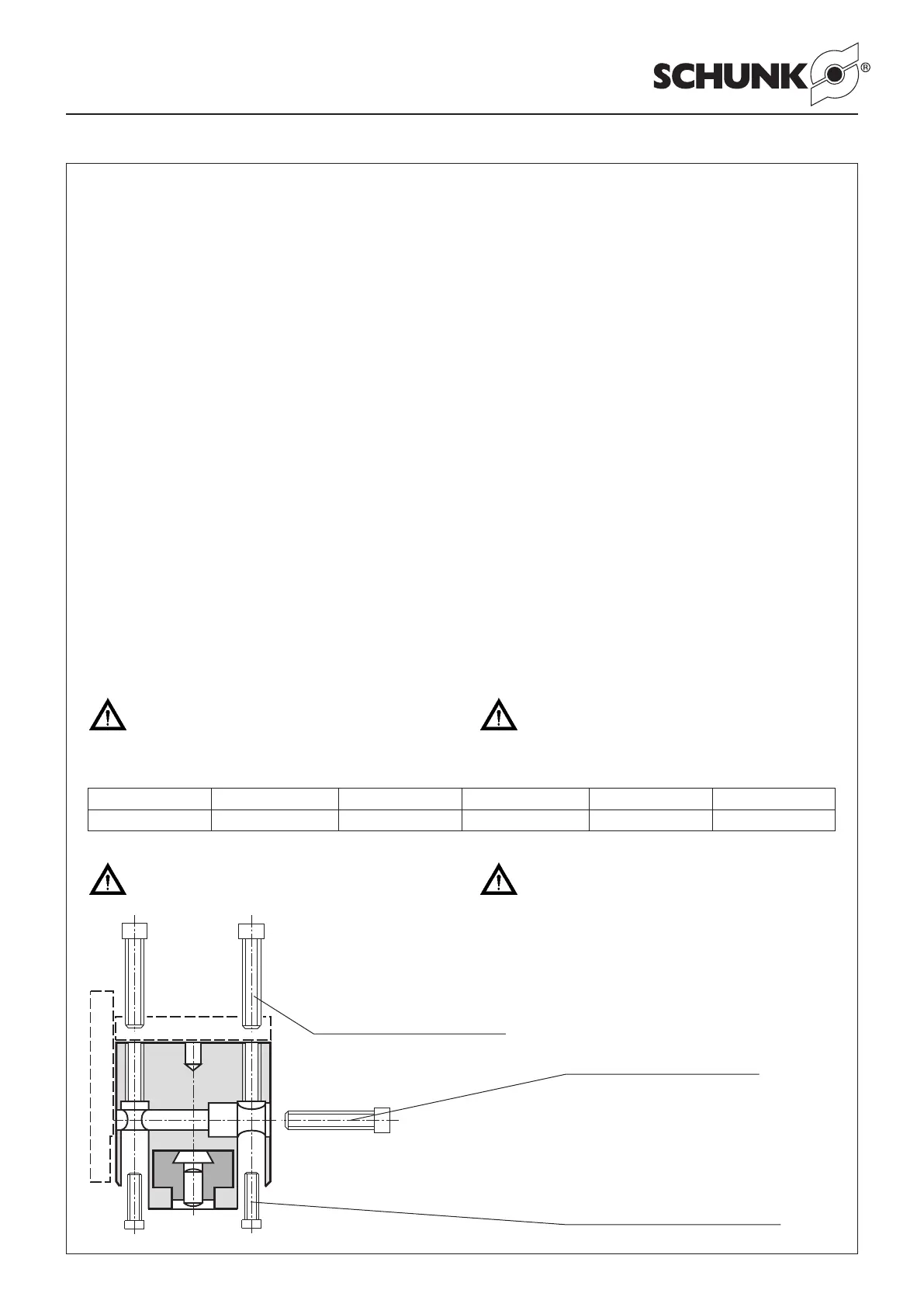
Locate the gripper by means of the two locating bores against its
bottom side or side face (two dowel pins in the enclosed pack):
PGN 50 PGN 64, PGN 80 PGN 100 PGN 125, PGN 160 PGN 200 PGN 380
Ø 3H7 Ø 4H7 Ø 5H7 Ø 6H7 Ø 8H7 Ø 10H7
ACHTUNG!
Bei seitlicher Befestigung muss die Adapterplatte
über den Befestigungsbohrungen abgesetzt werden
um ein Verklemmen der Grundbacken zu verhindern.
CAUTION!
In case of lateral fastening, the adapter plate must
have an undercut above the fastening bores in order
to avoid a jamming of the base jaws.
PGN 50 4 x M4
PGN 64 / PGN 80 4 x M5
PGN 100 4 x M6
PGN 125 / PGN 160 4 x M8
PGN 200 4 x M10
PGN 300 4 x M16
PGN 380 4 x M20
PGN 50 4 x M 3 x 25
PGN 64 4 x M 4 x 16
PGN 80 4 x M 4 x 20
PGN 100 4 x M 5 x 25
PGN 125 / PGN 160 4 x M 6 x 30
PGN 200 4 x M 8 x 40
PGN 300 4 x M12 x 55
PGN 380 4 x M16 x 76
PGN 50 2 x M3
PGN 64 2 x M4
PGN 80 2 x M5
PGN 100 2 x M6
PGN 125 / PGN 160 2 x M8
PGN 200 2 x M10
PGN 300 2 x M12
PGN 380 2 x M16