17
Montage- und Betriebsanleitung
für 2-Backen-Parallelgreifer Type PGN
Assembly and Operating Manual for
for 2-Finger-Parallel-Gripper Type PGN
12. Zubehör (auf besondere Bestellung)
Benötigen Sie mehr Informationen über die Handhabung von
Sensoren, wenden Sie sich vertrauensvoll an Ihren SCHUNK-
Ansprechpartner oder nutzen Sie unsere Download-Möglich-
keiten unter www.schunk.com>Produkte >Automation> Zubehör
12.1 Näherungsschalter
Technische Daten:
Spannung: 10 – 30 V DC
Restwelligkeit: ≤ 15%
Schaltstrom max.: 200 mA, kurzschlussfest
Schalthysterese: ≤ 15% vom Nennschaltabstand
Temperaturbereich: – 25°C bis + 70°C
Schaltfrequenz max.: 1000 Hz
Spannungsabfall ca.: 1.5 V
Schutzart
nach DIN EN 60529: IP 67*
*für die Rundsteckverbindung nur im verschraubten Zustand
12. Accessoires (upon separate order)
If you would like more information on the operation of sensors,
please contact your SCHUNK representative. Information is also
available for download at
www.schunk.com>Products>Automation>Accessories
12.1 Proximity switch
Technical data:
Supply voltage: 10 – 30 V DC
Operation voltage: ≤ 15%
Max load current: 200 mA, short circuit proof
Hysterisis: ≤ 15% of nominal sensing distance
Range of operat. temp.: – 25°C ... + 70°C
Max operat. frequency: 1000 Hz
Output transistor
voltage approx.: 1.5 V
Protect. class DIN EN 60529: IP 67*
*for concentric plug and socket only in screwed-in position
Type ABCd
1
d
3
d
4
d
5
d
6
d
7
d
8
d
9
l
1
l
2
l
4
l
5
l
6
Schraube 1 Schraube 2
H7 H7 Screw 1 Screw 2
DIN EN ISO 4762
PGN 50 45 32 27 -- -- 21,0 8 -- 4.5 3 -- -- 35 22 5 4,5 M 4 x 25
PGN 64 56 40 30 -- -- 26,0 10 -- 5.5 4 -- -- 42 27 66,0 M 5 x 30
PGN 80 66 46 60 66 6.6 34,0 10 M 6 5.5 4 33 52 52 32 86,0 M 5 x 60 M 6 x 40
PGN 100 80 53 60 80 9,0 42,0 11 M 8 6.6 5 41 66 66 38 10 7,0 M 6 x 60 M 8 x 40
PGN 125 104 64 60 -- -- 52,0 15 -- 9,0 6 -- -- 82 45 10 9,0 M 8 x 60
PGN 160 125 78 70 -- -- 64,0 15 -- 9,0 6 -- -- 100 56 12 9,0 M 8 x 70
PGN 200 150 100 70 150 11,0 90,0 18 M 10 11,0 8 89 130 130 70 16 11,0 M 10 x 80 M 10 x 55
PGN 300 210 140 68 200 11,0 127.5 26 M 10 17.5 10 126 180 180 96 16 17.5 M 16 x 70 M 10 x 40
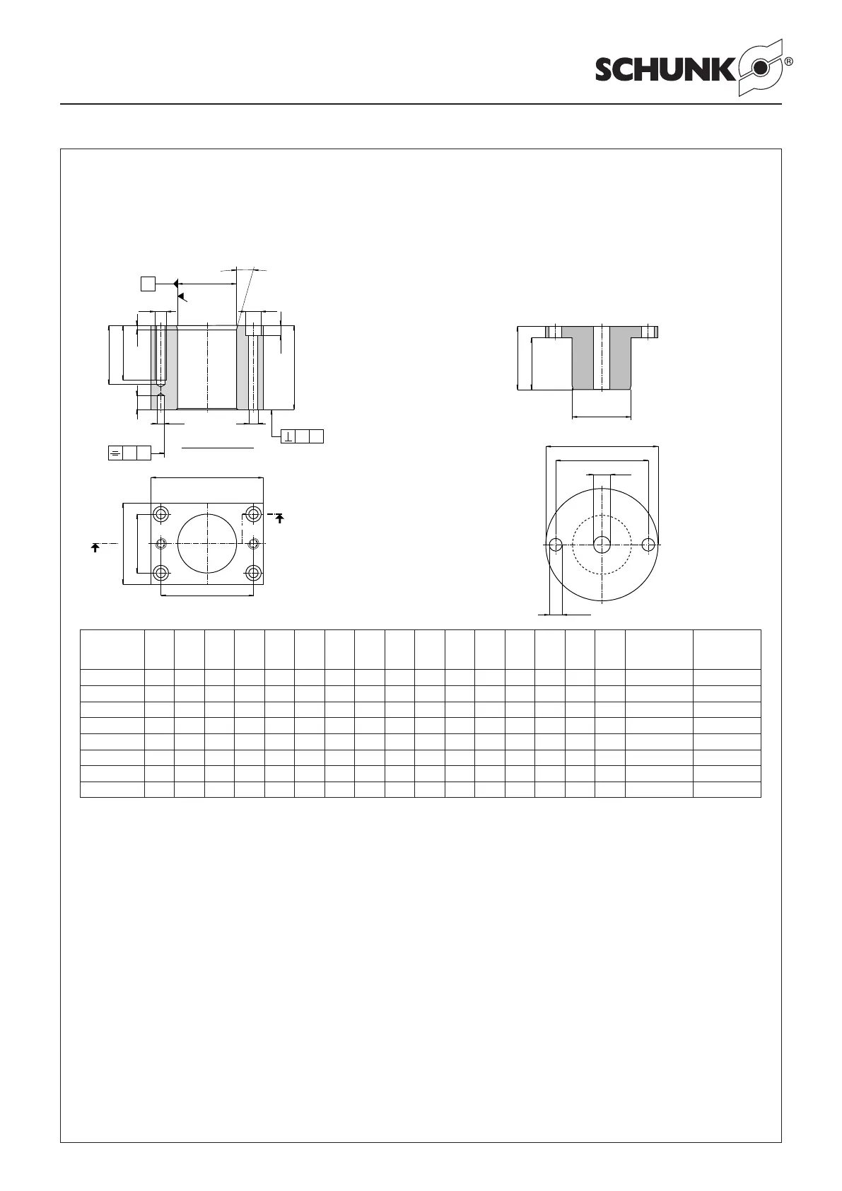
11. Montagevorrichtungen 11. Mounting devices
Vorrichtung 1 (Mat.: 16 Mn Cr5)
Mounting device 1 (Mat.: 16 Mn Cr5)
Vorrichtung 2 (Mat.: 16 Mn Cr5)
Mounting device 2 (Mat.: 16 Mn Cr5)
A
d
l
d
d
d
d
C
5
8
7
6
5
4
H7
H7
0.02
A
A
0
.02
1
5°
0.8
3
40
35
(
2x)
Schnitt / Cut A – A
l
6
A
B
l
l
2
4
A
A
(
± 0.02 für/ for Ø d
8
H7
)