SERVICE TRAINING
Service Manual
35
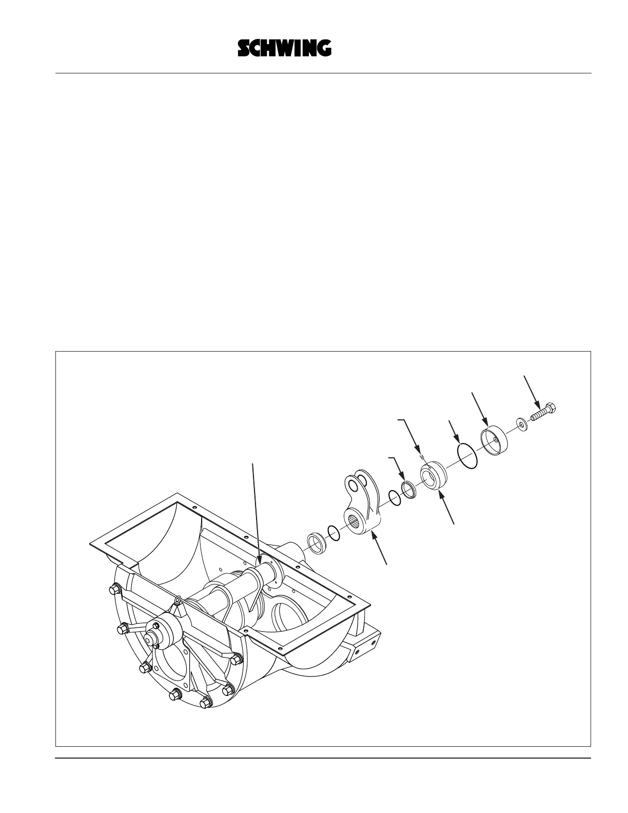
Rock Valve
Placing the Counter-Nut at the lever side:
Only the E-Rock Valve requires an additional Counter-Nut to compensate for internal thrust forces when the system is
in operation. The Counter-Nut can only be adjusted after the swivel drive is completely assembled. The Counter-Nut
has a pitch of 2 mm.
1. Place the Ring and Lever supplied with the O-rings onto the Swivel Shaft. The parts are in the right position if the
marked points (at the face) are matching.
2. Insert Ring into the Lever and watch out for the O-ring.
3. Screw on the Counter-Nut till it hits the Ring and make it hand tight.
4. Screw back the Counter-Nut by 1/4 turn and measure the gap. (approx. 0.5mm).
5. Secure the Counter-Nut by it’s 3 worm screws.
6. Place the Cover over the Counter-Nut and secure with Bolt. Don’t forget the O-Ring.
Counter Nut
Cover
O-Ring
Bolt
Swivel Shaft
Worm Screws
Insert Ring
Lever