14
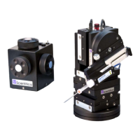
Figure N: PatchStar (left hand view), indicating rotary stage dovetail screws and removing
the rotary base.
2. Ensure that the 2 set screws that fix the rotary stop ring are loose by turning them
anti-clockwise, thus enabling the upper plate to rotate 360º.
Figure O: Rotary base, with set screws indicated
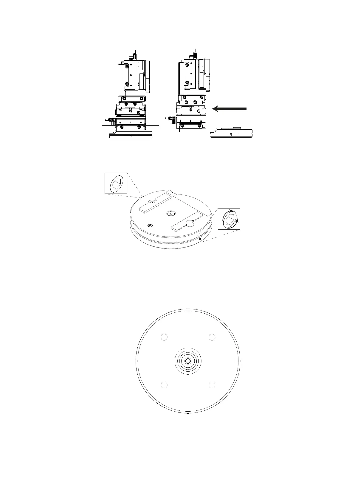
3. There are 4 mounting holes in the lower plate of the base that are accessed by
rotating the upper plate relative to the lower plate. Insert two M6 or ¼”-20 socket
head cap screws in two of the mounting holes. Now position the rotation plate in the
desired location and tighten the two screws.
Figure P: Lower surface, rotary base
4. Rotate the upper plate to reveal the other two mounting holes. Insert and tighten
two more screws.