15
5. In the reverse of step 1, slide the PatchStar assembly back onto the rotary base
and tighten the 2 dovetail locking screws on the Y axis (green).
3.2.2 Setting the rotational stops on the rotary base
The rotary base allows the PatchStar to be rotated between two magnetic stops 100° apart.
The magnetic stops provide enough force to hold the PatchStar in place for the application
but can be easily moved by hand between stops without having to undo any locking
mechanism or use any tools. The magnetic stops are moved together to set up the
positioning of the PatchStar.
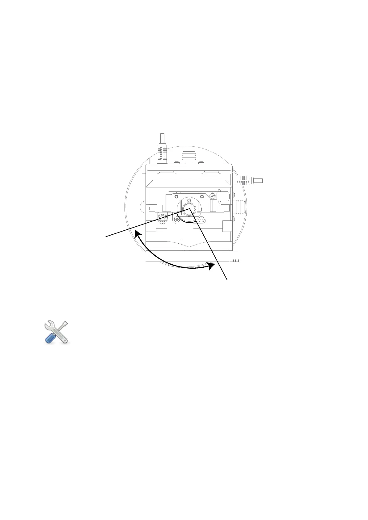
Figure Q: View from above, showing fixed degree of movement between the adjustable
magnetic stops
The following steps should be undertaken with the PatchStar fitted onto a rotary
base, which in turn has been fixed to the mounting surface. Please unplug all
cables from the breakout box before undertaking this process to prevent twisting
the cables – remember to power off the 1U rack controller before removing these
cables.
Right PatchStar
1. Ensure at least one of the grub screws in the rotary base is tight and then move the
PatchStar clockwise until it hits the stop.
2. Loosen the grub screw and move the base into the required position for the experiment.
3. Tighten the grub screw and check you can rotate the Patchstar anti-clockwise away from
the experiment to the other stop.
Left PatchStar
1. Ensure at least one of the grub screws in the rotary base is tight and then move the
PatchStar anti-clockwise until it hits the stop.
2. Loosen the grub screw and move the base into the required position for the experiment.
Fixed at
100°
Magnetic Stop at
Patching Position
Magnetic Stop at
Exchange Position