13
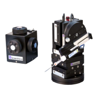
Figure L: Left hand view, fitting the Z axis (red) to the L-bracket
5. Slide the low profile bracket (1) onto the X axis (blue) and tighten the dovetail
screws on the long edge of the low profile bracket (2)
.
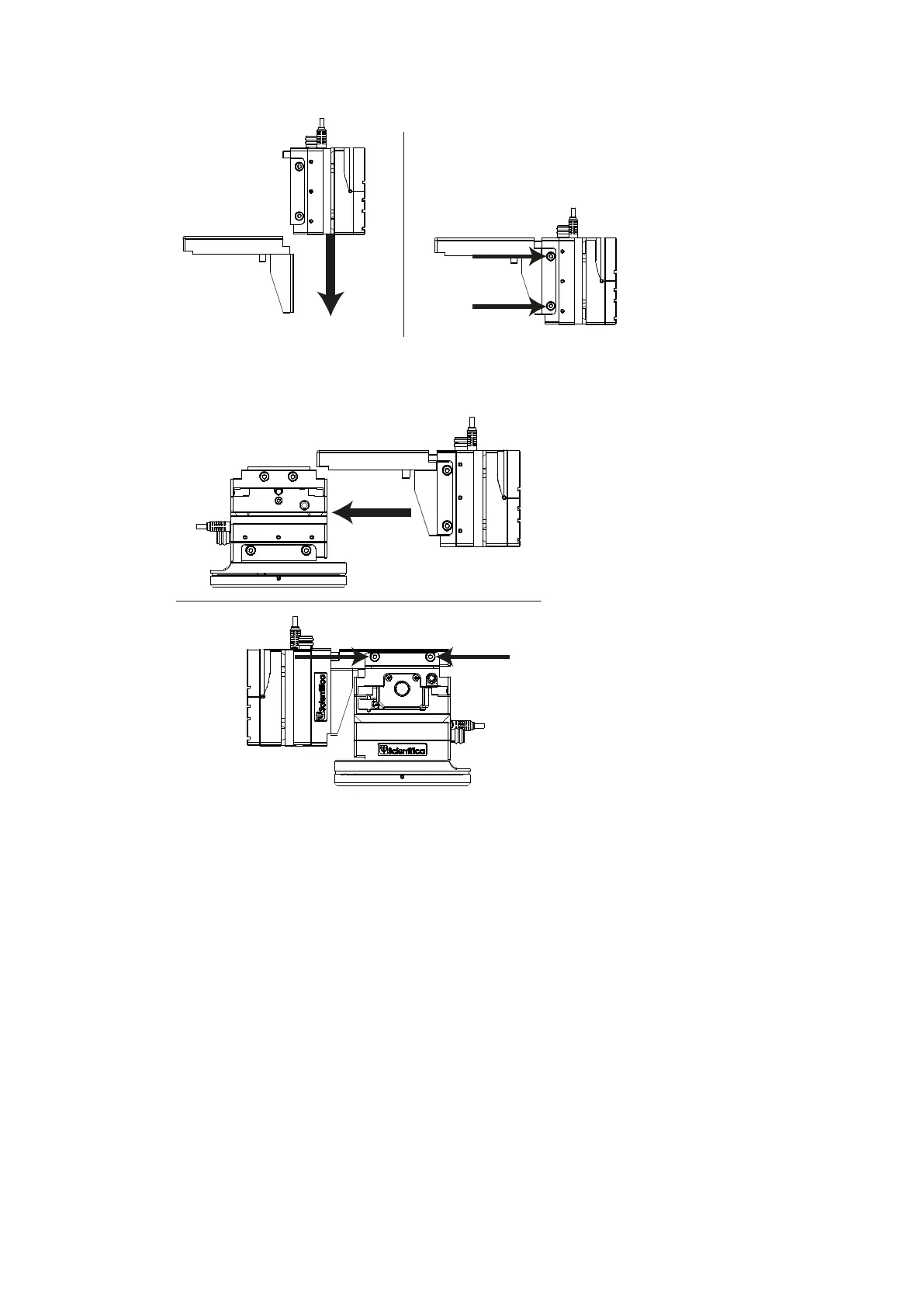
Figure M: Fitting the Z-axis onto the lower half of the PatchStar
3.2 Mechanical mounting and positioning of the PatchStar
3.2.1 Mounting the PatchStar using the rotary base
The PatchStar is designed to mount to either a metric or inch spaced location using M6 or
¼”-20 socket head cap screws (supplied). The rotary base is used to secure the manipulator
to the user’s table or platform.
1. Remove the manipulator assembly from the rotary base by loosening the two
dovetail locking screws on the Y axis (green) using the 3mm allen key supplied (1)
and sliding the complete assembly off the base (2)