23
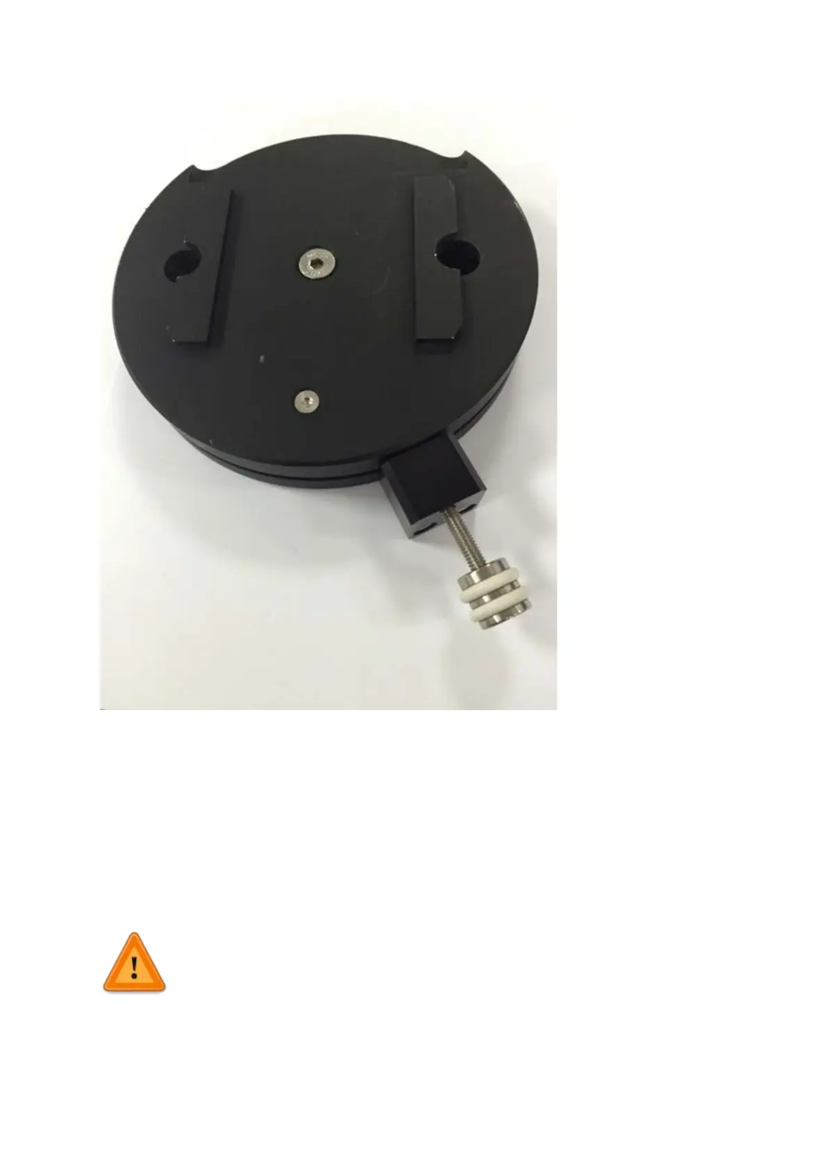
Figure A1: fully assembled thumbscrew locking base
3.3 Electrical setup of the PatchStar
To operate as a system the PatchStar will require connecting to a control rack and user
interface. There is also an optional connection via USB for PC control using Linlab software.
Ensure mains disconnect for external mains power supply outlet for the Scientifica Control
Rack is accessible. There is no integrated mains disconnect located within the PatchStar
unit.
The PatchStar on its own is not functional. It must always be connected to
Scientifica Control Rack, which must be connected to an earthed mains socket
to perform its normal function. When using multiple Control Racks each unit
must
be connected to individual mains power outlet on a separate
circuit. Each power cable must be connected to an earthed
mains power supply.