7
3.1 Removing the shipping brackets
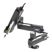
All motorised stages will be shipped with red brackets to prevent component damage in
transit. Before proceeding, remove the red shipping brackets from the sides of the UMS
using the supplied hex key set.
There are six countersunk holes on each side of the stage (12 in total) securing the brackets
in place; these can be removed using a 4 mm Allen key.
Important: Retain these brackets for future transit or return of the
equipment. Component damage is highly likely if these are not fitted
during shipping.
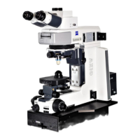
3.2 Electrical set up of the UMS
To operate as a system the UMS/XY Stage will require connecting to a control rack and user
interface. There is also an optional connection via USB for PC control using LinLab software.
Ensure mains disconnect for external mains power supply outlet for the Scientifica Control
Rack is accessible. There is no integrated mains disconnect located within the UMS/XY
Stage unit.
The UMS/XY Stage on its own is not functional. It must always be connected to
Scientifica Control Rack, which must be connected to an earthed mains socket
to perform its normal function. When using multiple Control Racks each
unit must be connected to individual mains power outlet on a separate circuit.
Each power cable must be connected to an earthed mains power supply.
3.2.3 Control racks
For connecting the UMS/XY Stage to the Control Rack and user interface please see the
relevant Control Rack User Manual. 4.0 Operation Guide
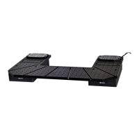
3.3 Mounting the UMS
3.3.1 Mounting the UMS to an anti-vibration table
The UMS is fixed to an anti-vibration table using the mounting holes in its lower section,
marked ‘A’ and ‘B’ in Figure C.
The UMS is attached to the anti-vibration table using either ¼ x 20 or M6 x 12 screws,
depending on the thread of the table.