P/N 595224-01 Rev E 7/12Page 31 of 32
FIGURE 25
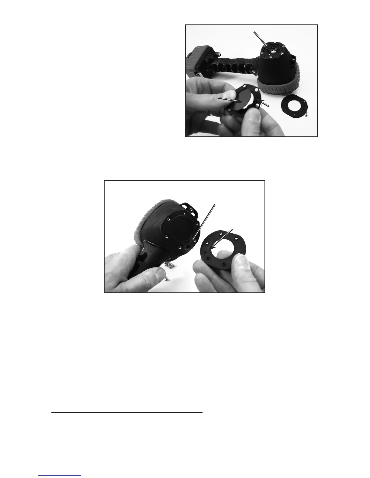
PIN ALIGNMENT
HOLE
ALIGNMENT
PIN
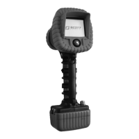
4. Fit the lens seal around the new
lens P/N 31000409 as shown in
FIGURE 24.
5. Place the new lens and lens seal on the front of the camera with the lens side in
rst. Align the six holes in the gasket with the holes in the housing. Make sure the
seal lays at with no kinks or wrinkles. Also make sure the pin alignment hole is
properly located. See FIGURE 25.
6. Place the lens cover on the lens seal with the alignment pin in the pin alignment hole
and align the six holes in the cover with the holes in the seal and the housing.
7. Replace the six (6) screws. Tighten screws to a torque of 6 to 8 Inch pounds. Use an
alternating pattern to assure even pressure on the seal. DO NOT OVER TIGHTEN.
Overtightening may damage the housing, lens cover, or seal.
8. Reinstall the LENS Boot with the two ats oriented above and below the lens. See
FIGURE 18.
9. Check the operation of the camera according to the USING THE EAGLE ATTACK
THERMAL IMAGING CAMERA section of this instruction to verify the operation
before returning the camera to service.
FIGURE 24
LENS
SEAL
LENS
CAMERA
CORE
ADDITIONAL REPLACEMENT PARTS
If you have any questions regarding other replacement parts or accessories, contact your
authorized SCOTT distributor, or contact SCOTT at 1-800-247-7257 (or 704-291-8300
outside the continental United States) or visit our web site at www.scottsafety.com.
 Loading...