P/N 595224-01 Rev E 7/12Page 14 of 32
USING THE EAGLE ATTACK THERMAL IMAGING CAMERA
1. Hold the EAGLE ATTACK Thermal Imaging Camera by the handle with the display
side toward you.
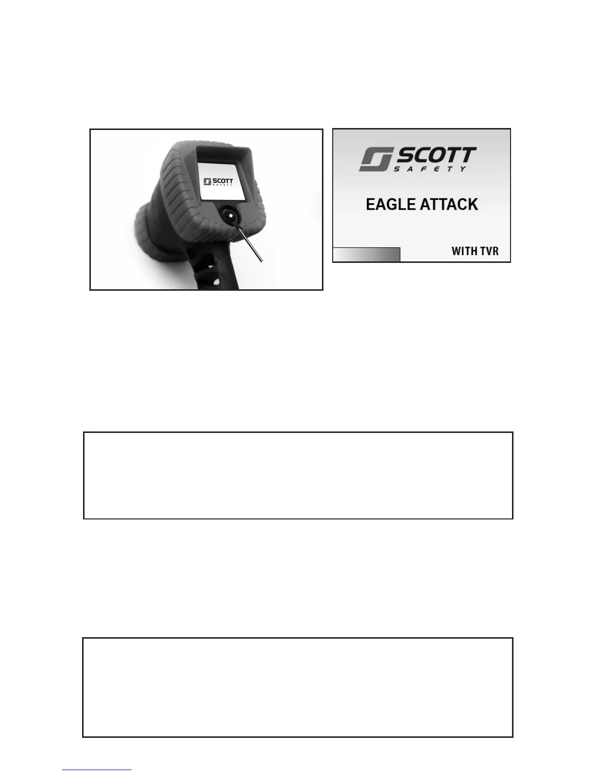
2. To turn ON the EAGLE ATTACK Thermal Imaging Camera, press and release the
POWER button below the display. The initialization screen will appear followed by
the thermal image. See FIGURE 7.
3. The EAGLE ATTACK Thermal Imaging Camera “sees” temperature differences
(infrared radiation) rather than visible light. The display screen shows shades of
gray from black to white. Warmer objects appear on the display screen as lighter
gray to white images while cooler objects appear darker gray to black. Compare
FIGURES 8 and 9.
NOTE
WHEN NOT IN USE, POSITION THE CAMERA WITH THE LENS POINTED DOWN
TO REDUCE RISK OF DIRECT EXPOSURE TO THE SUN.
CAUTION
DO NOT POINT THE EAGLE ATTACK THERMAL IMAGING CAMERA DIRECTLY AT THE
SUN. DO NOT POINT THE CAMERA AT HEAT SOURCES IN EXCESS OF 2700 °F / 1500
°C FOR EXTENDED PERIODS OF TIME. DOING SO MAY RESULT IN AN AFTER IMAGE
ON THE DISPLAY THAT COULD CAUSE TEMPORARY REDUCTION IN PERFORMANCE
OF THE CAMERA. IF THIS OCCURS, DO NOT USE UNTIL PERFORMANCE HAS
RETURNED TO NORMAL.
WARNING
BEFORE ENTERING A POTENTIALLY HAZARDOUS SITUATION, TURN ON AND TEST
THE THERMAL IMAGING CAMERA TO CONFIRM IT IS OPERATING PROPERLY.
FAILURE TO CONFIRM THE THERMAL IMAGING CAMERA IS OPERATING PROPERLY
MAY PLACE THE USER AT HIGHER RISK IN DANGEROUS SITUATIONS WHICH COULD
RESULT IN SERIOUS INJURY OR DEATH.
The appearance of the initialization screen will vary depending on the camera ver-
sion and the options installed:
– If the camera is the TAC (Temperature Awareness Colorization) version, a yellow
to orange color bar will appear in the lower left of the display.
– If the camera is equipped with the TVR Thermal Video Recorder option, “WITH
TVR” will appear in the lower right of the display.
Always turn ON and test the EAGLE ATTACK Thermal Imaging Camera before
entering a potentially hazardous situation to conrm it is operating properly.
FIGURE 7
POWER
BUTTON
INITIATION SCREEN SHOWN
WITH BOTH TAC VERSION
AND TVR OPTION
 Loading...