2
This document is the property of SDMO Industries.
Any communication, reproduction, publication, even partial, is forbidden, except with the written authorisation of the owner.
List of figures
Figure 1 - integration of the APM303 .............................................................................................................................................. 3
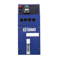
Figure 2 - front panel of the APM303 .............................................................................................................................................. 5
Figure 3 - viewing data ................................................................................................................................................................... 7
Figure 4 - main ................................................................................................................................................................................ 7
Figure 5 - current and voltage ......................................................................................................................................................... 7
Figure 6 - outputs ............................................................................................................................................................................ 7
Figure 7 - mechanical values .......................................................................................................................................................... 7
Figure 8 - meters ............................................................................................................................................................................ 8
Figure 9 - events and anomalies ..................................................................................................................................................... 8
Figure 10 - navigating through the stack .......................................................................................................................................... 8
Figure 11 - information available on screen 6 ................................................................................................................................. 8
Figure 12 - INIT ............................................................................................................................................................................... 8
Figure 13 - appearance of an alarm ................................................................................................................................................ 9
Figure 14 - appearance of a fault .................................................................................................................................................. 10
Figure 15 - an alarm displayed on the measurements screen ...................................................................................................... 11
Figure 16 - main menu .................................................................................................................................................................. 12
Figure 17 - setting principle........................................................................................................................................................... 16
Figure 18 - rear panel and connections .......................................................................................................................................... 17
Figure 19 - three phase 3P+N (4 wires) ........................................................................................................................................ 17
Figure 20 - three phase 3P (3 wires) ............................................................................................................................................ 17
Figure 21 - two phase 2P+N (3 wires) .......................................................................................................................................... 17
Figure 22 - single phase 1P+N (2 wires) ....................................................................................................................................... 17
Figure 23 - stored flat .................................................................................................................................................................... 19
Figure 24 - stored at an angle ....................................................................................................................................................... 19
Figure 25 - antistatic plastic bag ................................................................................................................................................... 19