9
LEROY-SOMER
2011.03/ g
Installation and maintenance
LSA 47.2 - 4 POLES
ALTERNATORS
3742 en -
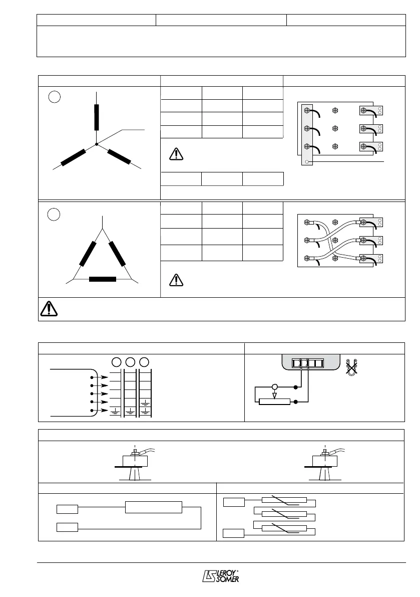
3.3.2 - Terminal connection: 6 wire (not possible with the R 250)
Connection codes Voltage L.L Factory connection
3-phase
N
T1
T4
T3
T6
T5
T2
L1(U)
L3(W)
L2(V)
D
NDE
L1(U)
L3(W)
T1
T4T3
T6
T5
T2
L2(V)
F
Single-phase
or 3-phase
(
*
)
Winding
60 Hz50 Hz
380 - 415 380 - 480
440
380 - 416
-
-
-
6S
7S
8S
Winding
60 Hz50 Hz
R 450 voltage sensing:
0 => (T3) / 220 V => (T2)
9S
600
220 - 240
220 - 240
220 - 277
240 - 254
-
-
6S
7S
8S
Winding 9: R 450 voltage sensing + transformer (Diagram on request)
NDE
L1(U)
L2(V)
L3(W)
T4
T6
T5
T1
T2
T3
N
L1(U)
L2(V)
L3(W)
T4
T6
T5
T1
T2
T3
In case of reconnection, ensure that AVR voltage sensing is correct!
The factory can supply a set of flexible shunts and special connection links as an option for making these connections (*).
R 450 voltage sensing:
0 => (T3) / 380 V => (T2)
Operating phases: L2 (V), L3 (W) single phase
3.3.3 - Option connection diagram
R 791 T interference suppression kit (standard for CE marking)
Remote voltage potentiometer
Black
Black
Black
Blue
White
Connections
A D F
T1 T1 T1
T2 T2 T2
T3 T3 T3
N N
Voltage adjustment
via remote potentiometer
ST4
6-wire
Current transformer connection (optional)
Anti condensation heater Thermistor (PTC) temperature
Neutral
link
- PH 1
In - Secondary 1 A
Coupling D
P1
P2
T4
12-wire
Neutral
link
- PH 1
P1
P2
Coupling D & A
T10
In - Secondary 1A
(coupl. D)
Ph1
Ph2
Ph3
103
104
130 C blue wire
150C black wire
180 C red/white wire
101
102
250W - 220 V
 Loading...