Do you have a question about the SDMO R 340 U and is the answer not in the manual?
General advice for operating and maintaining the generating set correctly, including safety instructions.
Explains safety notices and symbols used on the equipment for danger identification and action.
Essential safety guidelines and regulations for installing and maintaining generating sets.
Advice on personnel training, facility operation, safe practices, and maintenance procedures for generating sets.
Details risks associated with carbon monoxide in exhaust gases and safe handling of fuels, emphasizing ventilation.
Covers hazards from corrosion inhibitors, anti-rust products, and glycol, emphasizing safety precautions.
Outlines dangers of operating near explosive products and risks associated with hot parts, fuel, and battery gases.
Discusses electrical safety, compliance with standards, cable types, and correct connection procedures for generating sets.
Provides first aid instructions for electric shock victims, including resuscitation and moving the victim safely.
Safety procedures for unloading and moving generating sets, ensuring proper lifting equipment and ground support.
Explains how to identify generating sets and their components using identification plates.
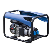
Identifies major components of the generating set through a diagram and numbered list.
Details technical specifications for the generating set, including dimensions, weight, noise level, and output data.
Information on recommended fuel types and consumables, including oil grades and coolant specifications.
Provides detailed specifications for oil grades, including properties and uses.
Details specifications for cooling fluids, including properties, approvals, and handling recommendations.
Instructions and safety measures for safely unloading generating sets from transport supports.
Detailed steps for unloading generating sets using slings or a forklift truck.
Guidelines for selecting an appropriate location for the generating set, considering ventilation, access, and noise.
Information on electrical connections, cable sizing, and safety guidelines for generating sets.
Discusses protection against power surges and the potential installation of lightning conductors.
Steps for correctly coupling a trailer to a tow vehicle, including safety checks.
Pre-towing checklist for trailer and generating set enclosure, including wheel tightness and lights.
Details operation procedures for "on-site" and "on-road" trailers, including speed limits and tyre checks.
Steps for implementing the trailer installation, including ground preparation and positioning.
Table listing common trailer faults, their origins, and recommended repair solutions.
Visual representation of the electrical connections for the trailer lighting system.
Technical data for complete wheels, including dimensions, load, and pressure.
Checks to verify that all installation requirements and general recommendations are met.
Post-start checks on the generating set, covering mechanical, electrical, and safety aspects.
Detailed guide to operating the generating set using the TELYS control panel, covering all functions.
Details the presentation and components of the TELYS control panel, including buttons and indicators.
Explains pictograms displayed in zone 1 of the TELYS control panel screen and their activation conditions.
Details alarm and fault pictograms displayed in zone 2 of the TELYS control panel screen.
Explains pictograms and data displayed in zone 3 of the TELYS control panel screen for different operating states.
Describes messages and information displayed in zone 4 of the TELYS control panel screen.
Step-by-step guide for starting the generating set, including pre-start checks and system operations.
Procedures for safely switching off the generating set, including manual and automatic methods.
How to view and interpret alarms and faults displayed on the generating set control panel.
Explains how alarms and faults are displayed on the screen and how to access help messages.
Describes how the system indicates simultaneous alarms and faults, and how to navigate the fault list.
Explains engine fault code standardization and terminology used by different manufacturers.
Procedure for resetting the horn after an alarm or fault activates it.
Introduction to the MICS Kerys system, its modules, and operating conditions.
Overview of the MICS Kerys system architecture, modules, and operational modes.
Specifies the environmental and mechanical conditions for operating the MICS Kerys system.
Lists the standards and directives to which the MICS Kerys system components comply.
Details the description of the KERYS system, identifying hardware components.
Explains how to identify MMI module, base module, and their respective references and batch numbers.
Describes how to identify software versions for the base, MMI, regulation, and protection modules.
Details the specifications and features of the Man Machine Interface (MMI) display and keypad.
Explains the different types of screens (home, navigation, operation) and how to navigate through the MMI.
Outlines the operating principles of different configurations for solo and power plant generating sets.
Outlines the operating principles of different configurations for solo and power plant generating sets.
Describes the configuration for a solo generating set without an inverter, detailing automatic and manual operation.
Explains power plant configurations with multiple generating sets in parallel, including coupling principles and wattmetric control.
Details recommendations and procedures for connecting generating sets according to various configurations.
Crucial safety recommendations to follow before performing any work on the generating set connections.
Table outlining connection requirements for different generating set configurations (solo, power plant).
Explains the importance and method of earthing generating sets, including rod length based on ground type.
Guides on passing power cables through access hatches and connecting them to busbars and the application.
Refers to wiring diagrams for client terminal block connections based on selected configurations.
Overview of the operation and setting menus, including the layout of main menus.
Displays the hierarchical structure of the main menus and sub-menus for operation and settings.
Instructions for setting regional parameters such as display language, date, and time.
Screen that enables project identification for customer service queries, providing site and connection details.
Explains the main screen displaying electrical parameters and how to navigate through operating menus.
Guide for choosing application configurations for solo generating sets and power plants, including specific settings.
Guide for choosing application configurations for solo generating sets and power plants, including specific settings.
General section on using the generating set.
Procedure for selecting the priority generating set within a power plant configuration.
Detailed instructions for starting, performing tests, and stopping the generating set in manual and automatic modes.
Information on optional features for rental configurations, such as damper valve and air preheating.
Reminder about the importance of the maintenance schedule and how environmental conditions affect intervals.
Detailed maintenance tasks for the engine, specifying inspections (I) and replacements (R) at various intervals.
Maintenance recommendations for the alternator, including bolt tightness, general condition, and electrical connections.
Guidelines for storing and transporting batteries, emphasizing cool, dry conditions and vertical positioning.
Procedure for putting batteries into service, including filling with acid and initial connections.
Table detailing battery checks based on acid density, charge status, and voltage.
Information on charging batteries, especially those that are highly discharged or sulphated, to prevent damage.
Lists common battery faults, their probable origins, and recommended measures or observations for correction.
Crucial safety information, including warning symbols and their meanings, and general safety precautions.
Detailed safety rules for daily checks, carbon monoxide poisoning, cooling system, fuel system, and operation.
General advice on care and maintenance, including starting the engine, lifting, fire/explosion risks, and batteries.
Describes the Diesel Control Unit panel, its buttons, and navigation elements.
Explains the main menu structure and sub-menus available on the DCU, including engine data and setup options.
Instructions on how to use the preheat function, including its activation and timing.
Explanation of the governor mode and its settings for controlling engine speed.
How to access and interpret diagnostic information, including fault codes and error messages.
Procedure for resetting trip data, such as fuel consumption and engine hours.
Guide to setting up various parameters in the engine's control system, including language and customer parameters.
Instructions for adjusting display settings, including contrast and backlight brightness.
Information displayed on the DCU, related to engine hardware, software, and dataset identifiers.
Displays engine data such as RPM, coolant temperature, and fuel level.
Describes the multi-mode display, showing information in different windows and toggling between them.
Details how to display trip data, including fuel consumption and engine hours.
Explains how to display engine data in graph format and select the desired information.
Accessing the configuration menu to set units, alarm status, service, and system parameters.
Lists active alarms and provides information on fault messages and their status.
Configuration options for language, display settings, and system parameters like time synchronization.
System settings including demo mode, fault resetting, and viewing hardware/software information.
Essential pre-start checks for oil, fuel, coolant levels, and general engine inspection.
Step-by-step instructions for starting the engine, with and without pre-heating, and explanations of indicator lights.
Preparations and precautions for starting the engine in cold weather conditions.
Instructions and warnings for starting the engine using auxiliary batteries, including connection procedures.
Steps to take before shutting down the engine, including warm-up and turbocharger cooling.
How to stop the engine using the controls, including disengaging the clutch and pressing the stop button.
Information about the location and function of the extra stop control.
A table correlating engine symptoms with possible causes and solutions for troubleshooting.
Explains the function of the CIU unit for displaying fault codes and managing diagnostic lamps.
Describes the DU display unit, its pop-up messages, and how to reduce engine speed.
Details the DCU display, showing engine data, faults, and how to access diagnostic information.
Procedure for resetting the diagnostic function memory and erasing fault codes.
Identifies major engine components and their locations using a numbered diagram.
Diagram showing the location of various sensors on the engine.
General inspection procedures for the engine, covering leaks, belts, and hoses.
Instructions for checking and changing the engine's air filter, including replacement criteria.
Guidance on inspecting the charge air pipe for leaks and tightening clamps.
Procedures for inspecting drive belts and alternator belts for tightness and condition.
Step-by-step instructions for changing the drive belt and alternator belt.
Information on oil change intervals, recommended oil types, and procedures for checking and topping up oil.
Detailed steps for changing the engine oil, including draining and filter replacement.
Instructions for changing the oil filter and by-pass filter, including cleaning and tightening.
Information on the fuel system, including warnings for fire hazards and fuel filter replacement procedures.
Steps for changing the fuel pre-filter, including seal lubrication and leak checks.
Procedures for draining condensate and fuel from the system, including using electric drain nipples.
Steps for bleeding the fuel system to remove air and ensure proper fuel flow.
Information on the engine's internal cooling system, coolant types, and maintenance recommendations.
Instructions for mixing coolant with water, emphasizing correct proportions and safety warnings.
Procedures for checking and topping up the coolant level in the system.
Steps for draining the coolant from the system, including safety precautions and checking for deposits.
Instructions for cleaning the charge air cooler, recommending mild detergents and avoiding high-pressure washers.
Procedure for changing the coolant filter, including safety measures and leak checks.
Guidelines for cleaning the cooling system to maintain performance and prevent freezing.
Information on the engine's electrical system, including main switch, fuses, and electrical connections.
Instructions for using the main switch, including safety warnings about disconnecting power.
Information about the engine's fuses, their location, and troubleshooting for tripped fuses.
Checks and recommendations for electrical connections, emphasizing dryness and secure tightening.
Safety measures and procedures for battery maintenance, including handling, cleaning, and charging.
Instructions for filling the battery cells with electrolyte, including level marks and resting time.
Safety precautions and procedures for charging batteries, including charger suitability and connection methods.
Procedures for preparing the generating set for storage up to 8 months, including fluid conservation.
Procedures for preparing the generating set for storage exceeding 8 months, focusing on lubrication and fuel systems.
Steps for preparing the generating set after storage, including checks and restarts.
Specific conservation steps for lubrication and fuel systems for extended storage periods.
Technical specifications for various Volvo Penta engine models.
Details of the lubrication system, including oil capacity, pressure, filter types, and oil recommendations.
Information on the fuel system, including feed pressure, pump valve status, and fuel specifications.
Information on the cooling system, including pressure cap, coolant quantity, thermostat, and water quality standards.
Technical data for the electrical system, including system voltage, alternator specifications, and battery capacity.
Explains how to identify engine components using chassis and engine serial numbers, and product designations.
Outlines compliance with international standards and essential safety measures for alternator use.
Instructions for inspecting the alternator upon receipt for any transit damage.
How to identify the alternator using the nameplate and understanding its definition criteria.
Recommendations for storing alternators to prevent damage, especially to bearings.
Describes the primary applications for which these alternators are designed.
Lists restrictions on using the machine outside of compatible operating conditions.
Provides details on the electrical features of the LSA 46.2 alternator, including winding types and options.
Outlines the mechanical construction of the LSA 46.2 alternator, including frame and bearing details.
Covers the installation process for the alternator, including assembly and coupling procedures.
Instructions for assembling the alternator, emphasizing mechanical handling and tool requirements.
Essential checks to perform before the first use of the alternator, focusing on electrical and mechanical aspects.
Diagrams illustrating terminal connections for different alternator configurations.
Diagrams for optional connection setups, including interference suppression kits and remote voltage potentiometers.
Checks to ensure electrical installations and connections comply with regulations and diagrams.
Procedures for testing and setting up the machine for initial use after installation.
Guidance on adjustments made during testing, including drive speed and AVR settings.
Guidelines for servicing and maintaining the alternator, including safety measures and routine procedures.
Crucial safety measures to follow during servicing and troubleshooting to prevent accidents.
Routine maintenance tasks, including checks after start-up and bearing lubrication.
Procedures for identifying the source of malfunctions if the alternator does not operate normally.
Lists common mechanical defects in alternators, such as bearing issues and vibration, with their causes and actions.
Identifies electrical faults in alternators, their effects, and check/cause procedures.
Procedure for checking alternator winding insulation using a high voltage test.
How to check the diode bridge's functionality by verifying current flow direction.
Procedure for checking windings and diodes using separate excitation, with assembly diagrams.
Instructions for dismantling and reassembling the alternator, with warnings for warranty.
Lists the necessary tools for dismantling and reassembling the alternator.
Steps for replacing the Non-Drive End (NDE) bearing, including tool usage and heating procedures.
Steps for replacing the Drive End (DE) bearing, including shield and screw removal.
Procedure for dismantling the rotor assembly, emphasizing care and potential rebalancing.
Steps for reassembling the alternator machine after component replacement.
Procedure for dismantling and reassembling filters, including cleaning the filter element.
Instructions for the installation and maintenance of the Permanent Magnet Generator (PMG).
Table of average values for the alternator, including resistances, voltages, and weights.
Information on spare parts for alternators, including emergency kits and technical support.
Lists available first maintenance and emergency repair kits for alternators.
Details how to contact technical support for information and spare part orders.
Describes available accessories for alternators, such as space heaters and temperature sensors.
Provides exploded views and parts lists for single-bearing and double-bearing alternators.
Essential safety measures and warnings for installing, using, and servicing the R250 AVR.
Explains the SHUNT excitation system and its auto-excitation with the R250 voltage regulator.
Explains the SHUNT excitation system and its auto-excitation with the R250 voltage regulator.
Details the R250 AVR, including its characteristics, U/F and LAM functions, and options.
Lists the operating and storage temperatures, voltage regulation, and supply range for the R250 AVR.
Explains the U/F function and LAM settings, including threshold positions and their effects.
Describes R250 AVR options, including voltage setting potentiometers and external connections.
Details the characteristics of the Load Acceptance Module (LAM), including voltage drop and its role in speed variation.
Illustrates the typical effects of the LAM on voltage, frequency, and power during load changes.
Covers the installation and commissioning of the R250 AVR, including electrical checks and settings.
Ensures proper electrical connections and rotating switch selections for AVR installation and commissioning.
Step-by-step guide for setting up the R250 AVR, including initial potentiometer settings and engine speed adjustments.
Lists common electrical faults related to AVR operation, their effects, and check/cause procedures.
Information on spare parts for the R250 AVR, including designation and technical support contacts.
Specifies the designation, type, and code for the R250 AVR spare part.
Details how to contact technical support for information and spare part orders.
Spare parts for Leroy-Somer LSA462VL12 alternators, including diode bridge and varistor.
| Acoustic pressure level @7m | 68 dB(A) |
|---|---|
| Displacement | 296 cc |
| Fuel | Diesel |
| Power factor | 0.8 |
| Voltage | 230 V |
| Weight | 120 kg |
| Frequency | 50 Hz |
| Starting system | Electric |
| Engine Type | Diesel |
| Fuel Type | Diesel |
| Fuel Tank Capacity | 25 L |