13
LEROY-SOMER
2011.01/ h
Installation and maintenance
LSA 46.2 - 4 POLES
ALTERNATORS
3856 en -
4.5.1 - Checking the winding
You can check the winding insulation by
performing a high voltage test. In this case,
you must disconnect all AVR wires.
Damage caused to the AVR in such
conditions is not covered by our
warranty.
4.5.2 - Checking the diode bridge
A diode in good working order should allow
the current to ow only in the anode-to-
cathode direction.
4.5.3 - Checking the windings and
rotating diodes using separate
excitation
During this procedure, make sure that
the alternator is disconnected from any
external load and inspect the terminal
box to check that the connections are
fully tightened.
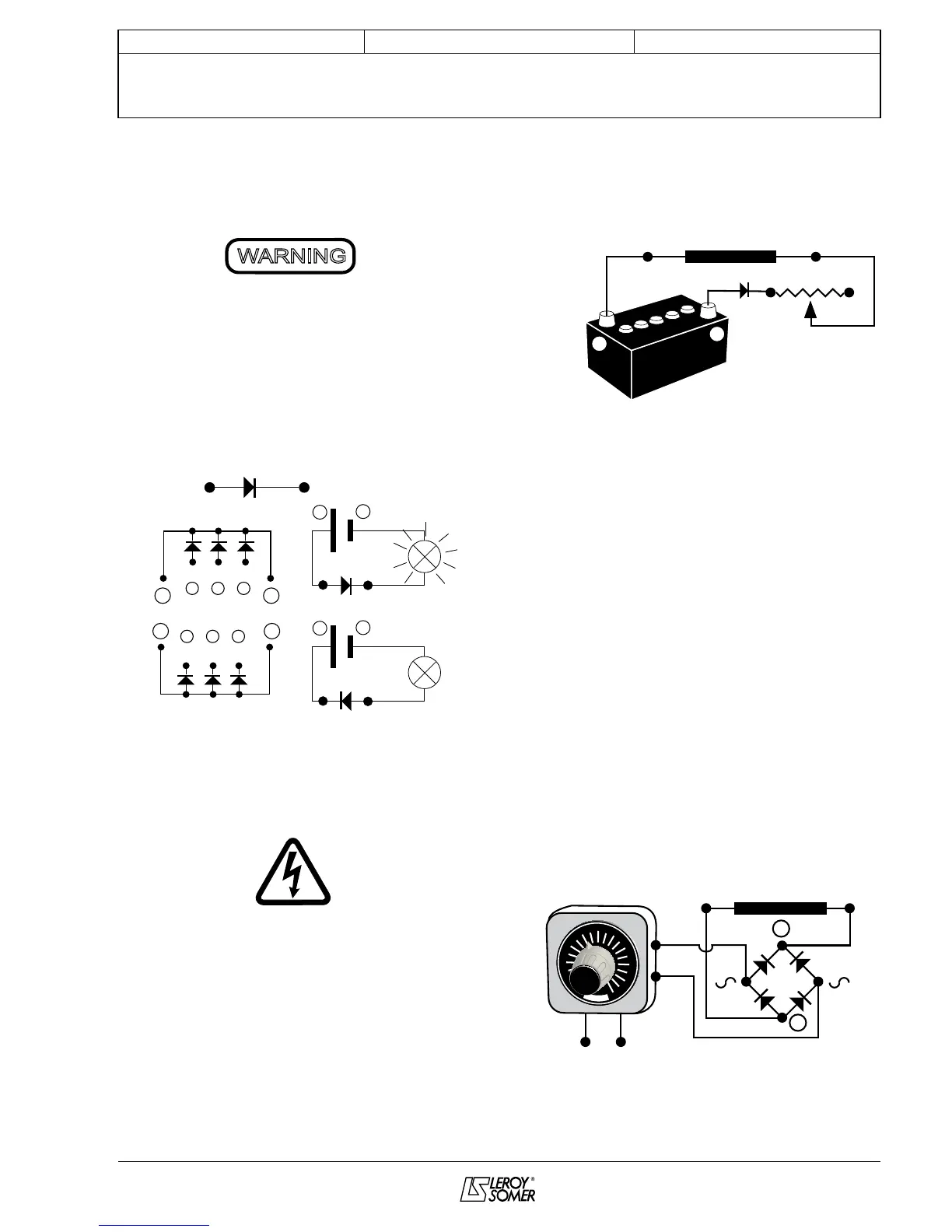
1) Stop the unit, disconnect and isolate the
AVR wires.
2) There are two ways of creating an
assembly with separate excitation.
Assembly A: Connect a 12 V battery in
series with a rheostat of approximately
50 ohms - 300 W and a diode on both exciter
eld wires (5+) and (6-).
6 - 5 +
Diode 1A
12V battery
Rh. 50Ω -300W
-
+
ASSEMBLY A
Exciter field
Assembly B: Connect a “Variac” variable
power supply and a diode bridge on both
exciter eld wires (5+) and (6-).
Both these systems should have
characteristics which are compatible with
the eld excitation power of the machine
(see the nameplate).
3) Run the unit at its rated speed.
4) Gradually increase the exciter eld
current by adjusting the rheostat or the
variac and measure the output voltages on
L1 - L2 - L3, checking the excitation voltage
and current at no load (see the machine
nameplate or ask for the factory test report).
When the output voltage is at its rated value
and balanced within 1% for the rated
excitation level, the machine is in good
working order. The fault therefore comes
from the AVR or its associated wiring (ie.
sensing, auxiliary windings).
Diode 1A
-
+
6 -
5 +
Variac
AC
220V
DC
12V
50
60
70
80
90
100
40
30
20
10
0
ASSEMBLY B
Exciter field