15
LEROY-SOMER
2011.03/ g
Installation and maintenance
LSA 47.2 - 4 POLES
ALTERNATORS
3742 en -
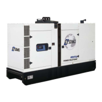
- Slide the threaded rod into the shield hole
to make it easier to assemble (see basic
diagram).
Rotor
NDE shield
Dowel
Nut
Threaded rod
4 78 36
- Fit the thrust bearing screws (78), remove
the threaded rod, t the other screw and
tighten up the assembly.
- Tighten the 5 bearing screws (37).
- Reconnect exciter wires E+, E-.
- Finish reassembling the cover.
When dismantling the shields, you will
need to change the antifriction bearings,
the “O” ring seal, the preloading (wavy)
washer and adhesive paste.
4.6.6 - Replacing the DE bearing
- Remove the air outlet grille (33).
- Remove the 6 screws (31) from the DE
shield and the 4 screws (62) from the inner
bearing retainer.
- Remove the shield (30).
- Take out the ball bearing (60) using a puller
with a central screw (see section 4.6.5).
- Fit the new bearing, after heating it by
induction to approximately 80 °C.
- Screw a threaded rod into the thrust
bearing (68).
- Ret the shield (30) on the machine.
- Slide the threaded rod into the shield hole
to make it easier to assemble (see basic
diagram).
- Tighten the bottom thrust bearing screws
(68), remove the threaded rod and t the
other screws.
- Tighten the 6 shield screws (31).
- Ret the air outlet grille (33).
4.6.7 - Dismantling the rotor assembly
- Remove the NDE shield (36) as described
in section 4.6.5.
- Remove the DE shield (30) as described
in section 4.6.6 if it is a double-bearing
machine.
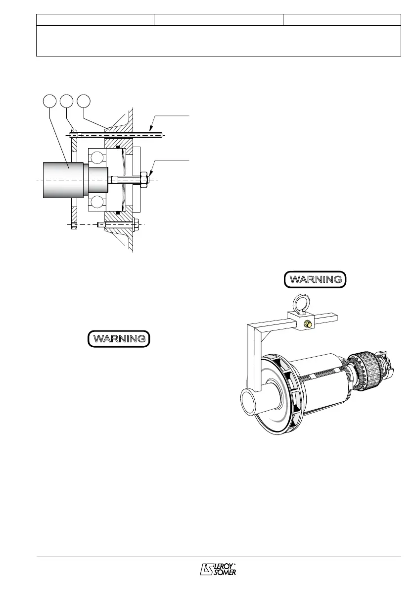
- Support the DE rotor (4) with a strap or with
a support constructed in accordance with
the following drawing.
- Move the strap as the rotor moves in order
to distribute the weight over it.
When dismantling the rotor involves
changing parts or rewinding, the rotor
must be rebalanced.
4.6.8 - Reassembling the machine
- Mount the rotor (4) in the stator (1) (see
drawing above) taking care not to knock the
windings.