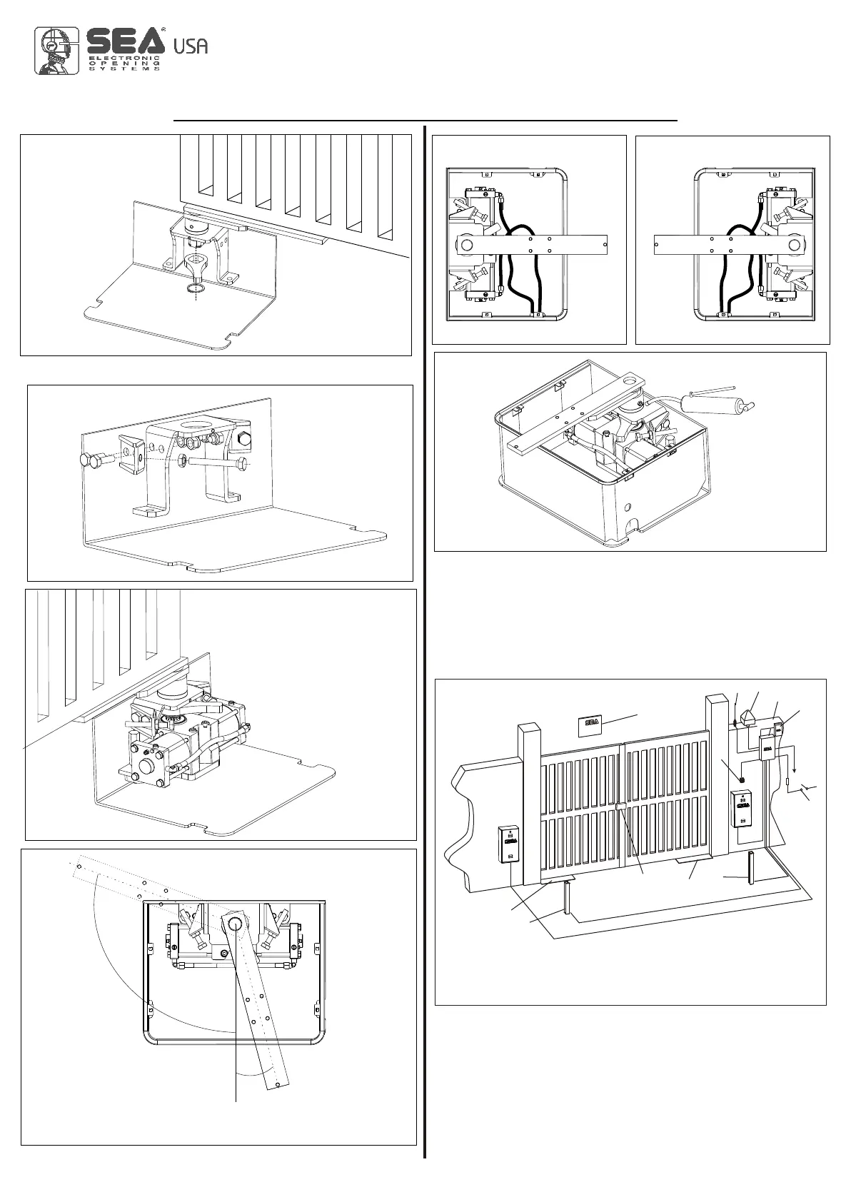
Fig. 49
Fig. 48
Fig. 51
0
-15°
105°
Fig. 52 Fig. 53
Fig. 50
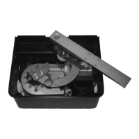
When putting in function the installation it is peremptory to
lubricate the box as in Fig. 54 until the grease comes out.
se grease typeDIN 51502 KP 2 N-20 - K 2 K-20). (U
Fig. 54
Fig. 55
1
2
3
4
2
5
6
7
8
9
10
11
15. CABLE LAYOUT (Fig. 55)
REV 00 - 03/2014
Max. Angle with mechanical stops kit
RIGHT
LEFT
Outside
Inside
Outside
Inside
1) Warning notice
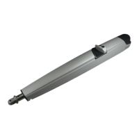
2) Jack 1600
3) Left photocell
4) Right photocell
8) Electronic control unit
9) Receiver
10) Differential switch
11) Electric lock (SB version only)
5) Key switch
6) Antenna
7) Flashing warning lamp
MECHANICAL INSTALLATION
International registered trademark n. 2.777.971
LYRA, JACK
6741178514