Fig. 14
Fig. 15
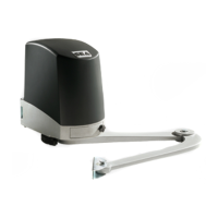
Fig. 18
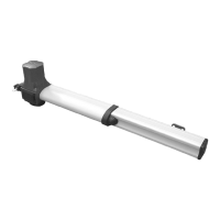
Fig. 16
Fig. 17
REV 00 - 03/2014
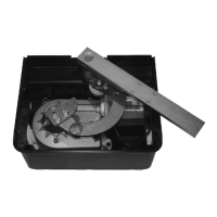
Fig. 13
=
=
Flexible pipe
for water
draining
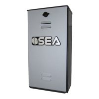
2.2. Inside the excavated pit you have to plan:
- rain water drainage;
- a water waste pipe in flexible plastic of about 1,57 inches of
diameter to put inside the provided hole of the box before it is
concreted (Fig. 13). It must be brought to the drain of the
sewer line;
- a sheath for the passage of the hydraulic tubes of about 1,25
inches of diameter which must be brought to the proximity of
the hydraulic unit box (Fig. 13).
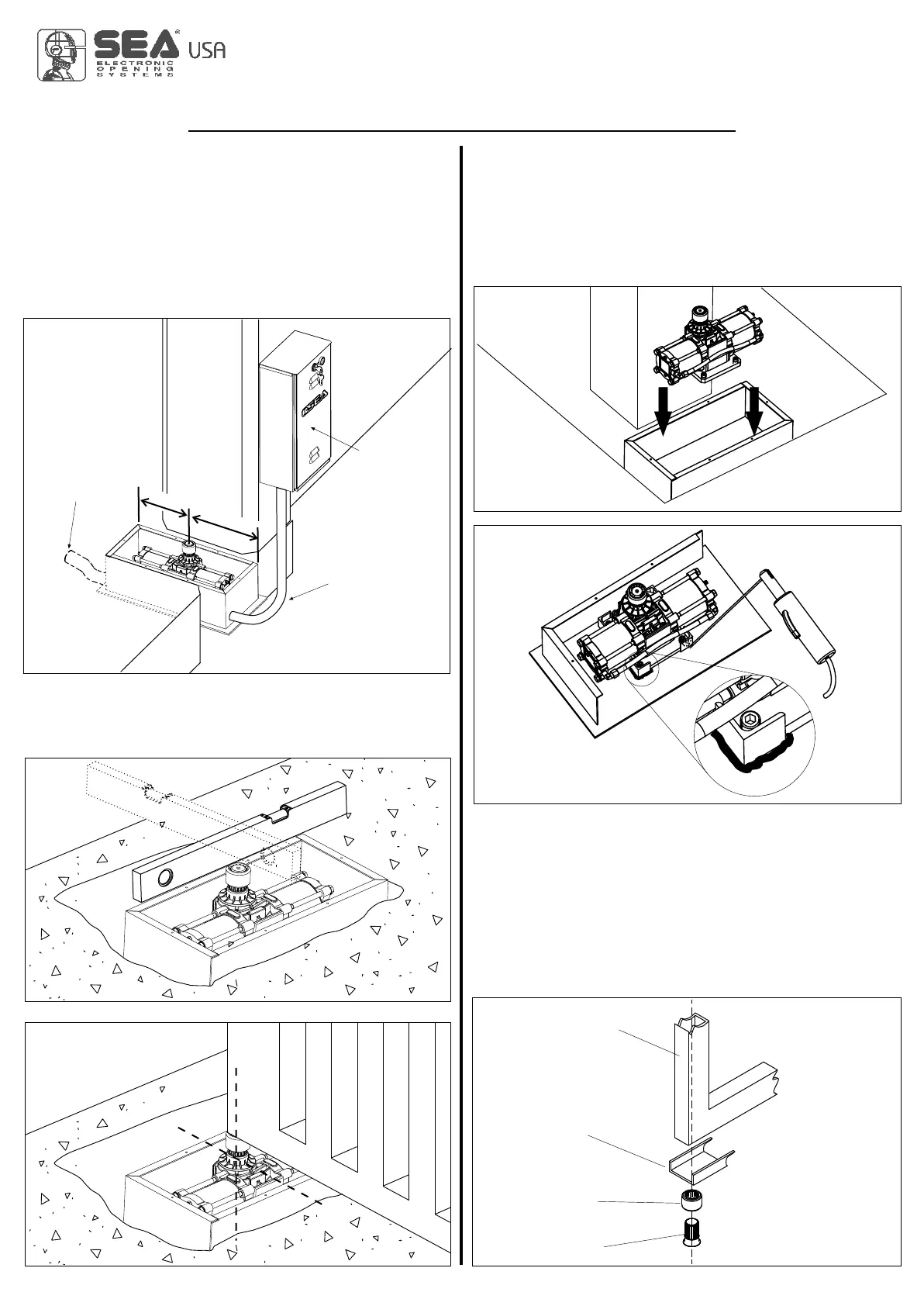
2.3. Before concreting the box, use a level to make it perfectly
horizontal to the ground (Fig. 14) and perpendicular to the axis of
the gate (Fig. 15).
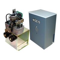
Hydraulic tubes
sheath
Hydraulic unit
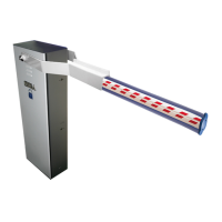
Pivot
Bush
U-shaped bar
Leaf
4. MOUNTING OF THE LEAF ON NON-
CARRYING BOX
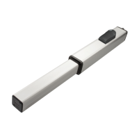
4.1. Insert the broached bush on the shaft of the jack.
Turn the shaft of the jack toward closing until it stops.
WARNING: For operators with brake make sure that the jack
has reached the stop and not the beginning of the
slowdown.
4.2. Go back about 5° and weld the bush to the U-shaped bar
(not supplied) and to the leaf of the gate (Fig. 18).
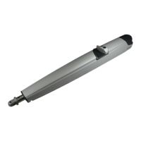
3. INSTALLATION OF THE OPERATOR
INSIDE THE NON-CARRYING BOX
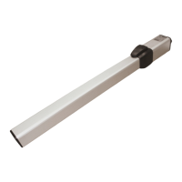
3.1. Place the jack inside the foundation box (Fig.16)
positioning the axis of the output shaft aligned with the axis of
the hinge of the gate and weld the four angular ends to fix the
same (Fig. 17).
MECHANICAL INSTALLATION
International registered trademark n. 2.777.971
LYRA, JACK
674117858