SCSI ID=0
SCSI ID=1
SCSI ID=2
SCSI ID=3
SCSI ID=4
SCSI ID=5
SCSI ID=6
SCSI ID=7
SCSI ID=8
SCSI ID=9
SCSI ID=10
SCSI ID=11
SCSI ID=12
SCSI ID=13
SCSI ID=14
SCSI ID=15
Parity enable
Term. power
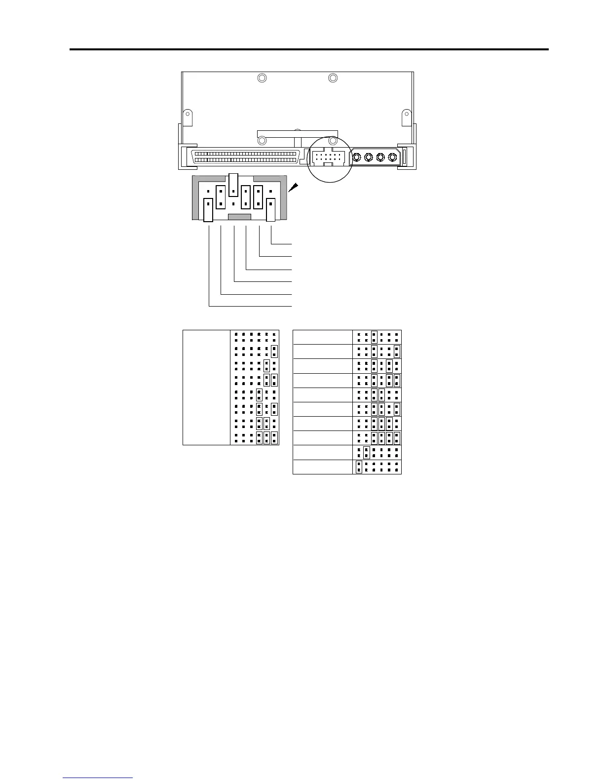
Default jumper settings shown
(SCSI ID 6, parity checking enabled,
and termination power disabled)
Pins: Function:
1-2 SCSI ID bit 0
3-4 SCSI ID bit 1
5-6 SCSI ID bit 2
7-8 SCSI ID bit 3
9-10 Parity checking
11-12 Termination Power
Figure 6. Jumper Settings for an Internal Drive
SCSI Address Selection (Pins 1 through 8)
You can select the SCSI address used by the drive by placing the appropriate
jumpers on pins pairs 1-2 through 7-8, as shown in Figure 6. The SCSI address
can also be selected remotely by connecting a SCSI address-selection switch to
pins 1 through 8.
Each SCSI device on a bus must have a unique SCSI ID. The SCSI controller or
host adapter generally uses ID 7. In some systems, the boot drive uses ID 0.
Note:
In an 8-bit SCSI mode, the drive only uses SCSI addresses 0 through 7.
Parity Checking (Pins 9 and 10)
If a jumper is installed on pins 9 and 10 (the default setting), parity checking is
enabled. If no jumper is installed, parity checking is disabled, but parity is still
generated by the drive.