INSTALLATION
MANUAL
Section 2: ELECTRICAL INSTALLATION
2.2 Electrical Equipment Power Connections
1. 230 VAC POWER SOURCE REQUIREMENTS
a. 230 VAC (nominal), 1 Phase, 50/60 Hz, 20 Amps.
b. With installations of more than one Seakeeper, a separate circuit breaker should be
used for each Seakeeper Motor Drive Box
2. DRIVE BOX AC POWER INPUT CONNECTION INSTRUCTIONS
a. Cable: 3 x 10AWG (3 x 6.0 mm
2
CSA), 10’ (3m) length, Seakeeper supplied pre-
installed.
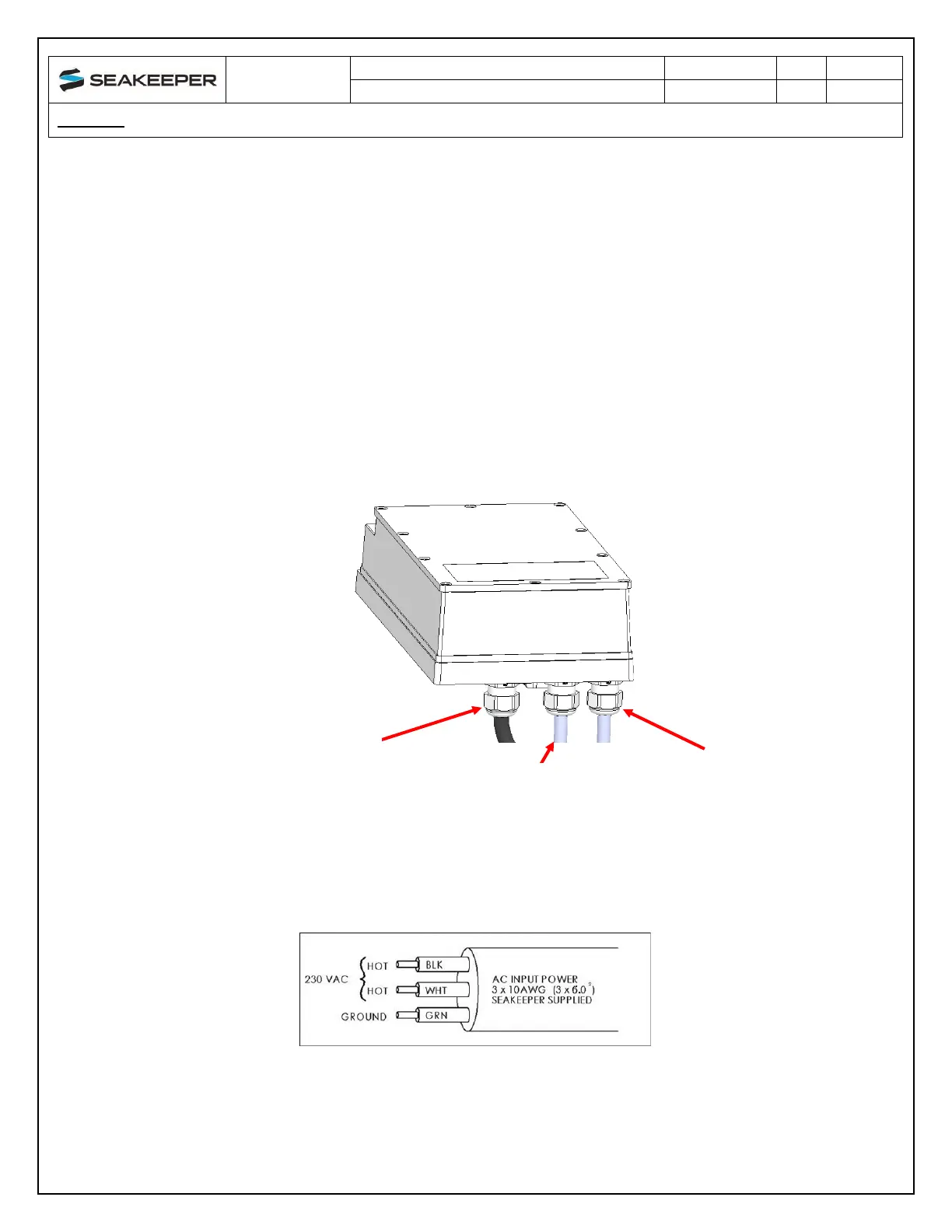
i. Locate CABLE 2 for AC power input to the Drive Box at the outward of three
cable glands.
INWARD CABLE GLAND
FOR DRIVE POWER
OUTPUT TO
SEAKEEPER
MOTOR
MIDDLE CABLE GLAND
FOR AC POWER
OUTPUT TO
SEAWATER PUMP
(CABLE 5)
OUTWARD CABLE
GLAND FOR AC POWER
INPUT
(CABLE 2)
FIGURE 2 – DRIVE BOX AC POWER INPUT & OUTPUT CABLE GLANDS
FIGURE 3 – CABLE 2 WIRE CONNECTIONS AT AC POWER DISTRIBUTION PANEL
ii. Connect 230 VAC wires in CABLE 2 to a 20 Amp, double-pole Circuit Breaker
at an AC power distribution panel according to Figure 3 above.