INSTALLATION
MANUAL
Section 3: COOLING INSTALLATION
3.0 Introduction
The Seakeeper 9 is shipped with the cooling circuit filled and ready for use. Only a quick
confirmation of glycol level is required.
Reference Drawings
90221 Seakeeper 9 Hardware Scope of Supply
90415 Seakeeper 7HD Hardware Scope of Supply
90257 Seakeeper 9/7HD Cable Block Diagram
90251 Seakeeper 9/7HD Cooling Water Schematic
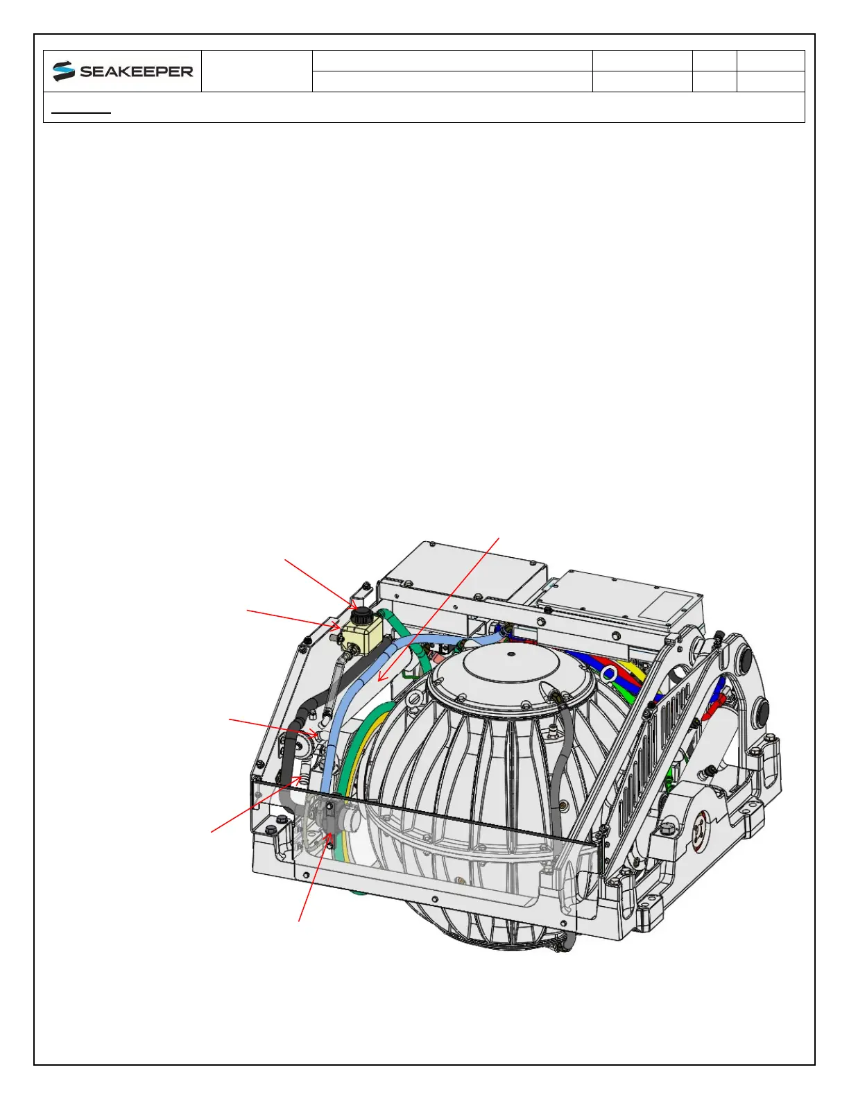
HEAT EXCHANGER
COOLANT FILL
COOLANT RESERVOIR
SEAWATER RETURN
(TOP BARB CONNECTION)
SEAWATER INLET
(LOWER BARB CONNECTION)
GLYCOL PUMP
FIGURE 1 – SEAKEEPER 9 COOLING COMPONENTS