INSTALLATION
MANUAL
Section 3: COOLING INSTALLATION
• After several minutes of running, press POWER ON/OFF button to turn
power off to the flywheel.
5) The cooling system is self-purging. If small amounts of air are in the system, they will
most likely be dislodged during the first sea trial. Recheck level after sea trial and add
fluid if required.
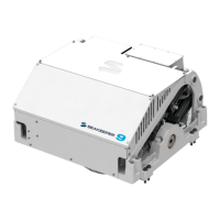
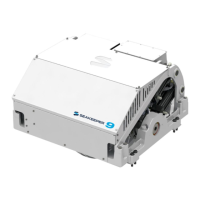
3.3 Connecting Seawater to Heat Exchanger
1) Connect seawater from installer supplied pump to lower 3/4” (19 mm) hose barb on heat
exchanger (See Figure 1). Use the same practices as other below waterline seawater
plumbing. Required flow rate is 4 GPM (16 LPM) minimum and 8 GPM (30.3 LPM)
maximum.
2) Connect seawater discharge to upper hose barb to overboard drain (See Figure 1).
Use the same practices as other below waterline seawater plumbing.
3) In addition to initial operation at dock, new Seakeeper installations should be checked
for minimum 4 GPM (16 LPM) flow while vessel is at speed and when backing down. If
no other method of confirming flow is available, discharge line may be temporarily
diverted to a bucket. Flow is calculated from time to fill a known volume. A self-priming
sea water pump (customer/installer supplied) may be required due to installation location
to maintain water flow in all underway conditions where cavitation near the intake may
occur and potentially cause an air-lock condition restricting sea water flow to the heat
exchanger.
4) Inspect raw water plumbing after sea trial for any signs of leakage.
5) Heat exchanger contains removable end-caps to provide access for cleaning the tube
bundle.