AG3000 INSTRUCTIONS
Seametrics • 253.872.0284 Page 13 seametrics.com
CONNECTIONS
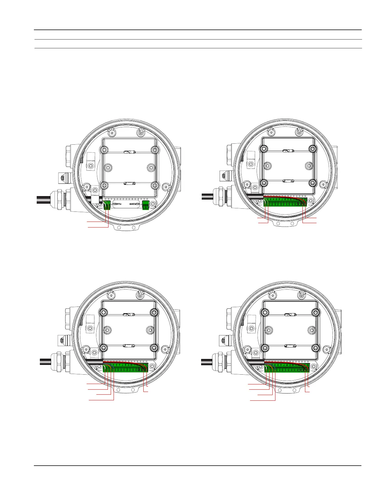
Wiring Diagrams
Battery Power with Pulse (BXX) DC Power with Pulse (D1X/D2X)
DC Power with Pulse and 4-20mA (D1L/D2L)
Unscrew the display lid and remove it. The display assembly is held in with 3 fasteners. If those fasteners are
steel screws (silver) remove them with a T-15 Torx driver and lift the diplay out of the meter. If the fasteners are
white Nylon tabs with exposed straight slots, simply grasp the two nger recesses in the display, then pop the
diplay up and out of the housing. Remove the 15 pin screw connector from its bag. Install the wires through
the cable glands and into the 15 pin screw connector in their respective locations. Plug the 15 pin screw
connector into its socket. Be sure all pins align properly and that the connector has not slipped to one side.
(C1=power/outputcable,C2=power/outputcable2)
DC Power with Pulse and HART/4-20mA (D1H/D2H)
White (C1) Pulse-
Green (C1) Pulse+
C1
White (C1) Pulse-: pn1
Green (C1) Pulse+: pn2
Red (C1) DC+: pn15
Black (C1) DC-: pn14
C1
White (C1) Pulse-: pn1
Green (C1) Pulse+: pn2
Orange (C1) 4-20mA+: pn3
Blue (C1) 4-20mA-: pn4
C1
Red (C1) DC+: pn15
Black (C1) DC-: pn14
White (C1) Pulse-: pn1
Green (C1) Pulse+: pn2
Orange (C1) 4-20mA+: pn3
Blue (C1) 4-20mA-: pn4
C1
Red (C1) DC+: pn15
Black (C1) DC-: pn14
 Loading...