AG3000 INSTRUCTIONS
Seametrics • 253.872.0284 Page 11 seametrics.com
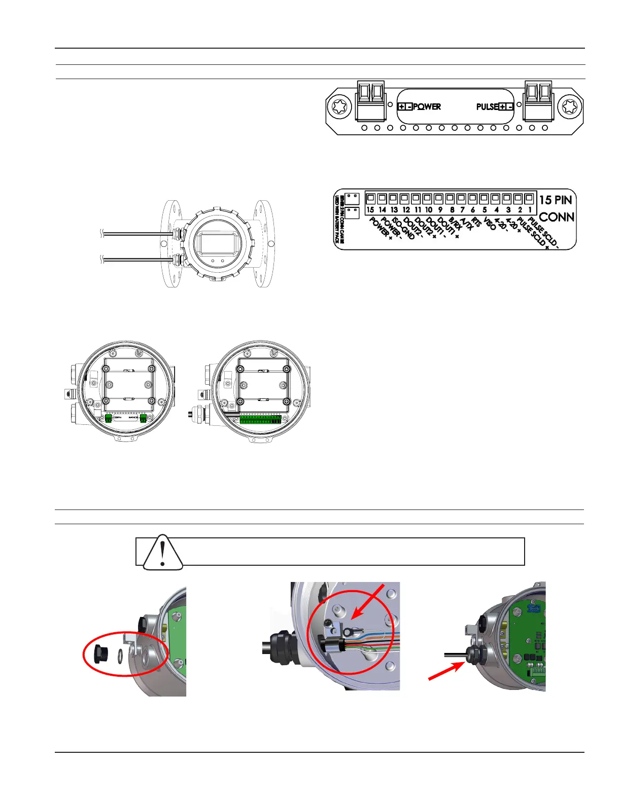
CONNECTIONS
Cable Gland Opening and Sealing
15PinConnectorforAG3000DCVersions
Two2-pinConnectorsforAG3000BatteryVersion
AG3000 General Cable Information
In the AG3000 meter, there are a maximum of two Power/
Output cables that can be installed. These cables contain
the wires for DC power and for any available options
(Modbus
®
, HART, 4-20mA, and scaled pulse). (See Sample
Cable Wiring Diagrams and Cable Wiring Table.) It is up to
the user to decide how to best organize the wiring for the
application.
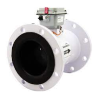
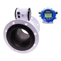
The AG3000 is available in either Battery or external DC
versions.
Power/Output Cable 2
Power/Output Cable 1
Integrated
Meter
Batteryversionwithtwo
2-pinconnectors
DCversionwitha15-pin
connector.(Yourmeter
mayhaveoneortwo
cableglands,depending
onconguration.)
WARNING: Improper sealing of glands or cables will invalidate any warranty.
Removeplug&o-ring.Insert
cablegland/strainrelief.Feed
cable through cable gland.
CRITICAL!
Torquecableglandsealing
nutto22in-lbs.
Clampcablewithstrainrelief
clips.Attachdrainwirelugto
bracket post.
Notethatwhenviewingtheconnectorsfromthe
frontofthemeter,thelabelswillbeupsidedownwith
numbering going from left to right.
 Loading...