Service Manual Replacement instructions
19.08.04/Rei 1 30-34-00-673 d
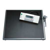
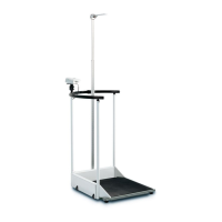
seca 664, 665
Removing the power supply unit / ESD protection measures (Page 7)
The power supply unit must not be connected.
We urgently recommend that you remove the battery pack before starting any work on the unit:
Remove the 2 screws (Item 7.11) and the battery cover (Item 7.12).
Pull the rechargeable battery connection apart (cable).
Remove the rechargeable battery pack (Item 7.8).
ESD protection measures must be taken whenever work is performed on electronic components.
Disassembly (the references to pages and items relate to the replacement instructions drawing, Pages 5-13)
1. Removing and dismantling the column (Page 5)
Disengage the cable (Item 5.3) under the scale.
Release the cable from the cable terminals.
Release the two screw connections (Item 5.1).
1.1 Dismantling the joint and locking unit (Page 12)
Remove the plug (Item 12.13).
Hold the bolt (Item 12.4) in the column tube (using suitable pliers which do not damage the surface of
the bolt) and unscrew the knurled nut (Item 12.1).
The thread is glued in place and difficult to slacken.
Remove the bolt and the compression spring (Item 12.3).
Turn the bracket (Item 12.9) so that the screw (Item 12.7) is accessible and slacken the screw
connection (Item 12.7). Hold the self-locking hex nut in the column tube using a suitable spanner.
Pull the cable (12.12) out of the unit.
Release the lock screw (Item 12.5) using a suitable tool.
Remove the threaded axle (Item 12.11) and remove the two slip rings (Item 12.8, 12.10) and the
bracket.
If required: Remove the slip ring (Item 12.2) (glued) and clean the bearing surface (Item 12.6).
1.2 Removing the display housing (complete with joint) (Page 12)
Remove the 3 screws (Item 12.14).
Pull the column off the bearing bush (Item 12.15) and the cable (Item 12.12).
1.3 Dismantling the display housing (Page 13)
Remove the screws (Item 13.1) and lift off the upper part of the housing (Item 13.9).
If required: Remove the membrane keyboard (Item 13.11).
Warning: The membrane keyboard is glued on and cannot be replaced in the same quality.
If required: Remove the film strips (Item 13.10).
Warning: The film strips is glued on and cannot be replaced in the same quality.
Depending on the model: Unsolder the cable (Item 13.12)
Remove the screws (Item 13.8).
Lift off the PCB (Item 13.7) and detach the cable’s plug-in connection (Page 12, Item 12.12).
Remove the cable through the central opening in the housing.
Lift off the upper guide rails (Item 13.6), the drawer (Item 13.4) and the lower guide rails (Item 13.3).
If required: Pull the battery compartment (Item 13.5) out of the drawer.
Depending on model: Remove the screws (Item 13.14). There could be spacers under the screw
heads. Lift off the PCB (Item 13.13)