Service manual Electronics description
21.11.08 / EE/Jensen 30-34-00-779
1
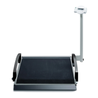
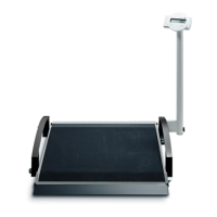
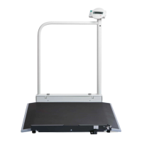
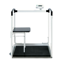
Servicing seca electronic modules
seca electronic modules allow you to measure the signals of the weight sensor and to display the
weight values resulting from this. Depending on the design of the scale, both functions can be
combined on one module or distributed on different modules.
The configuration and adjustment data is stored on the module to which the weight sensor will be
connected. If this module is replaced, the replacement module must be configured and adjusted. This
is done using a PC configuration program called “serva”. Modules that only perform display functions
can simply be replaced.
When accumulator batteries are connected to the relevant connections, these batteries are charged
by the power supply unit with a 40 mA trickle charging current. Therefore make sure never to connect
batteries to the connections provided for accumulator batteries as the batteries would be destroyed by
the charging current and run out.
If, instead of the original seca power supply unit, a power supply unit is used that supplies an output
voltage of more than 12V, the electronics can be destroyed. Warning: There are many 12V power
supply units that supply more than 12V if there is no sufficient load on them. Therefore make sure only
to use original seca power supply units. If the electronics module was damaged as a result of a wrong
type of power supply unit being used, it must be replaced. Electronics that were damaged in this way
will usually draw so much current from the power supply unit that the power supply unit will cease to
function after a short while.
Identifying defective load cells
If you assume that a load cell may be defective, it is not always easy, especially on scales with four
load cells, to determine which of them is faulty.
In many cases a digital multimeter will help.
Unsolder the load cells you suspect to be faulty one after the other and measure the resistance
between the different connecting leads. On load cells that are typically used in scales with four load
cells the reading should be approx. 1200Ω between the supply connections, approx. 1000Ω between
the outputs and approx. 850Ω between a supply line and an output line. For platform load cells which
are typically fitted in scales with just one load cell, the readings should be approx. 1/3 of these values.
It is even easier to determine which load cell is defective if an oscilloscope is available. As grounding
contact you can use the grounding connection of the power supply unit, battery or accumulator
battery. Use the measuring head to measure the operational amplifier’s output signal at pin 7 of the 8-
leg IC with the number 2051 or 1112 printed on it. Make sure to pierce the paint with the test probe.
On the oscilloscope you should now see recurrent ramps starting from a 2.5V line, the height of which
depends on the load on the load cells. When you press on a load cell, the corresponding ramp
increases. If load cells are defective, this is usually easy to identify. Some distort the signal to such an
extent that the ramps no longer start at 2.5V. If you press on all cells in succession you will see which
cell responds as it should and which cell causes an incorrect signal.