Service Manual Replacement instructions
19.08.04/Rei 2 30-34-00-673 d
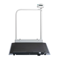
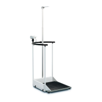
1.4 Removing the joint connection from the display housing (Page 12)
Dismantle the display housing as described under 1.3.
Remove the screws (Item 12.23).
Disengage the housing (Item 12.22) from the snap-in connection with the tilt stand (Item 12.20).
Remove the screws (Item 12.21) and lift off the tilt stand.
Remove the screws (Item 12.19) and lift off the plate (Item 12.18).
If required: Remove the pin (Item 12.16) and pull the pivot pin (Item 12.17) out of the bearing bush
(Item 12.15).
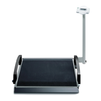
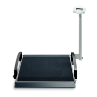
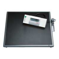
2. Removing and dismantling the frame (Page 5)
Release the 4 screw couplings (Item 5.2).
2.1 Removing the housing for the evaluation electronics and the battery pack (Page 6)
Remove the 2 screw couplings (Item 6.8) and lift off the housing (Item 6.9) and the supporting disks
(Item 6.10).
2.1.1. Dismantling the housing for the evaluation electronics and the battery pack (Page 7)
Remove the 4 screws (Item 7.1) and lift off the end plate (Item 7.2).
Remove the 4 screws (Item 7.3) and lift off the end plate (Item 7.4).
Warning: The housing is no longer held together.
Lift off the housing half (Item 7.5).
If not yet done: Remove the battery pack (Item 7.8).
Remove the filler pieces (Item 7.9).
Lift off the PCB (Item 7.7).
If required: Unsolder the load cell, mains socket and rechargeable battery cables from the board.
If required: Remove the PCB guard (Item 7.10).
If required: Remove the 2 screws (Item 7.11) and the battery cover (Item 7.12).
If required: Remove the cable gland (Item 7.13).
First of all, remove the ferrite from the cable of the mains socket (Page 8). Then pull out the cables of
the load cells and the mains socket.
If required: Remove the cable gland (Item 7.13).
2.1.2. Removing the rechargeable battery connection cable (Page 7)
If required: Unsolder the rechargeable battery cable from the PCB (Item 7.7).
2.2 Removing the holder for mains socket and bubble level (Page 6)
Remove the 2 screw couplings (Item 6.11) and lift off the holder (Item 6.12) and the supporting disks
(Item 6.13).
2.2.1 Removing mains socket and cable (Page 8)
Remove the screw (Item 8.4).
Remove the 2 screws (Item 8.1).
Remove mains socket and cable (Item 8.2). (For unsoldering see 2.1.1).
2.2.2 Removing a defective bubble level (Page 8)
Warning: Only remove the bubble level if it is defective, as destruction of the bubble level cannot be
avoided. A new bubble level can only be fitted by a skilled person working with great care!
Lever the bubble level (Item 8.6) out of the holder. Scratch the holder free and clean it.
2.3 Removing a load cell (Page 6)
Remove the 2 screw couplings (Item 6.1) and lift off the load cell cover (Item 6.2).
Remove the 4 nuts and washers (Item 6.3) and lift off the load cell (Item 6.4).