21
Mechanical Installation
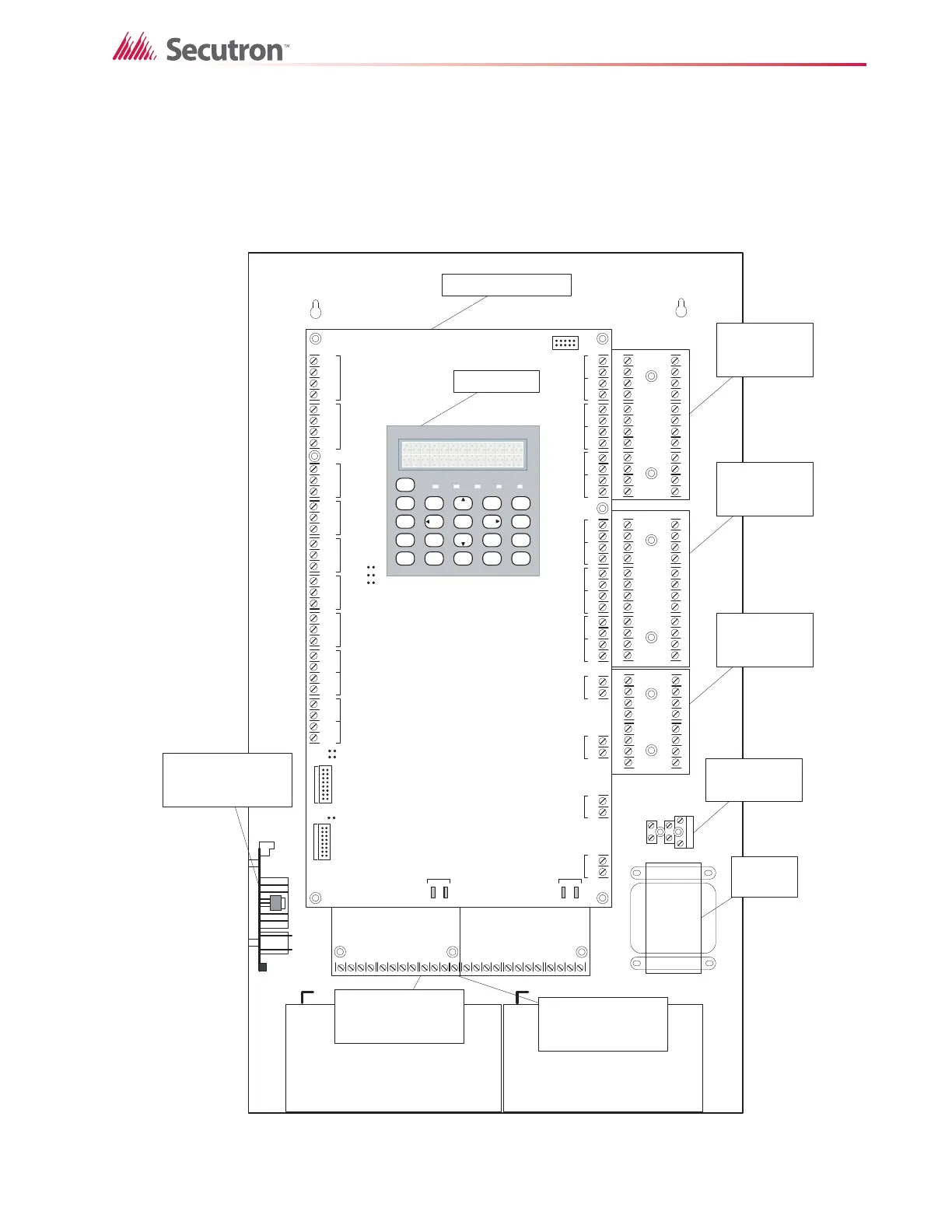
5.3 Installing the Adder Modules
MR-2300 Series Fire Alarm panels come pre-assembled with all components and boards
except for Adder Modules. Module installation locations are shown below. Refer to Figure 8
and Figure 9 for Jumper or DIP Switch settings and see “Field wiring” on page 29 for wiring
information.
Figure 6 Installation of Adder Modules for MR-2312 LCD Panels
S-+NC N OCNC NOCNC NOCNC NOC
+-+-COM(+)
COM(-)
TRLTRB RTRT
RTR T
RES CO RES C O
LINE1LINE 2
JW3
JW2
JW1
-+-+-+-+-+-+-+-+-+-+-+-+-+-+-+-+
DET 1DET 2DET 3DET 4DE T 5DE T 6DE T 7DE T 8DET 9DET 1 0DET 11DET 12SI G 1SIG 2SIG 3SIG 4
JW 6
JW 5
JW 4
TO PR -300 MOD ULE
T O RM-312/R M-306 RELAY
MODULE
RS-
485
AUX. REL AYALA RM
REL AY
SU P E RV IS O RY
RELAY
TR OUBLE
RELAY
AU X
SUPPLY
4- W I R E
SUPPLY
UNFILTERED
RTI
PORT
P
1
P
2
P
3
P
4
+
_
BATTERY SEC. TX
BATTERY BATTERY
CLASS-A converter
board for detection
circuits MR-2300- A
(6 circuits)
CLASS-A converter
board for detection
circuits MR-2300-A
(6 circuits)
CLASS-A converter
board for indicating
circuits MR-2300-NC4
(4 circuits)
Reverse polarity and city
tie module MR-2300-PR.
Mounted on hex spacer
with two screws provided
Relay Module MR-2306-R6
Mount relay module on the
left side using two screws
provided .
Relay Module MR-2312-R12
centre under main fire
alarm board using three
screws provided .
Transformer
Fuse and AC wiring
terminal
MAIN FIRE PANEL BOARD
SY ST EM
RESET
SI G N A L
SI L EN C
E
FI R E
DRILL
BUZZER
SI L EN C
E
LA MP
TEST
1
4
7
*
2
5
8
0
3
6
9
#
EN T ER
MENU
CANCEL
INFO
ABC DEF
GHI JKL MNO
PR S
TUV
WXY
QZ
A.C. ON ALARM SUPV TRBL CPU FAIL
SYSTEM NORMAL
18:01 MON 2003-04-05
LCD DISPLAY
 Loading...


