EasyManua.ls Logo

Secutron MR-2306-DDR

Secutron MR-2306-DDR
96 pages
To Next Page IconTo Next Page
Loading...
Installation and Operation Manual
LT-906SEC Rev. 3.2
January 2020
MR-2300 Series
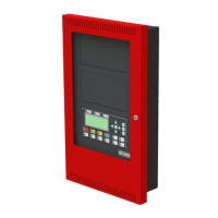
LCD Fire Alarm Control Panel

Table of Contents

Other manuals for Secutron MR-2306-DDR

Questions and Answers:

Secutron MR-2306-DDR Specifications

General IconGeneral
BrandSecutron
ModelMR-2306-DDR
CategoryControl Panel
LanguageEnglish

Summary

Industry Canada and FCC Notice

Notice for all MR-2300 Series Built-In UDACTs Sold in Canada

Regulatory notice for UDACTs sold in Canada.

Industry Canada Notice

Specific notices and cautions for Industry Canada compliance.

FCC Notice

Federal Communications Commission (FCC) compliance requirements.

Introduction

Overall Features

Overview of the MR-2300 Series Fire Alarm Control Panel's capabilities.

Overall Features

Detailed overview of the MR-2300 Series panel's features.

Conventions

Circuits

Definition of electrical interfaces for initiating, indicating, and relay functions.

Zone

Definition of a logical concept for a Fire Alarm Protected Area.

Events

Description of events displayed via the LCD.

Wiring Styles

Explanation of Class B and Class A wiring styles for circuits.

Wiring Styles

Explanation of Class B and Class A wiring styles for circuits.

System Components, Sub-Assemblies & Accessories

Main Fire Control Panel

Description of the main fire alarm control panel models.

Relay Module: 12 Relays

Details on the twelve-relay adder module.

Relay Modules: Six Relays

Details on the six-relay adder module.

Polarity reversalcity tie

Information on the polarity reversal and city tie module.

Remote Annunciator

Details on the remote annunciator module.

Smart Relay Module

Information on the Smart Relay Module.

Input Class A converter: Six Circuits

Details on the six-circuit Input Class A converter module.

Output Class A converter: four circuits

Details on the four-circuit Output Class A converter module.

Output Class A converter: two circuits

Details on the two-circuit Output Class A converter module.

Active end-of-line

Description of power-saving end-of-line resistors.

MR-2312-AT Remote Annunciator

Details on the MR-2312-AT remote annunciator.

Additional Fire Alarm System Accessories

Listing of other fire alarm system accessories.

Mechanical Installation

Installing the Enclosure

Instructions for mounting the fire alarm panel enclosure.

MMX-BBX-1024 DS and MMX-BBX-1024 DSR Mechanical Installation

Installation details for specific enclosure models.

Installing the Adder Modules

Procedures for installing adder modules into the panel.

Installing the Adder Modules

Procedures for installing adder modules into the panel.

DIP Switch and Jumper Selections for Main Board and Adder Modules

Main Fire Alarm Board

DIP switch and jumper settings for the main fire alarm board.

MR-2300-A Input Class-A Converter Adder Module

Configuration for the MR-2300-A input converter module.

Main Fire Alarm Board

DIP switch and jumper settings for the main fire alarm board.

Field wiring

Main Fire Alarm Board Field Wiring

Wiring diagrams for the main fire alarm board.

Initiating Circuit Wiring

Diagrams for wiring initiating circuits (Class B/D).

Indicating Circuit Wiring

Diagrams for wiring indicating circuits (Class B/Z).

Four Wire Smoke Detector Wiring

Wiring schematic for four-wire smoke detectors.

Dialer Wiring

Wiring connections for the on-board dialer.

Relay Adder Module Wiring

Terminal connections for relay adder modules.

Connecting to a 3 G4010 CF Interface Device

Guide for connecting the 3G4010CF interface device.

Polarity Reversal and City Tie Module (MR-2300-PR) Wiring

Wiring diagram for the MR-2300-PR module.

Power supply connection

Details on connecting the power supply to the panel.

Wiring Tables and Information

Tables with wiring gauge, run, and resistance limits.

Four-Wire Smoke Power (regulated)

Specifications for the regulated four-wire smoke detector power supply.

Supervised Auxiliary Power (regulated)

Details on the supervised auxiliary power supply.

Auxiliary Power (unregulated)

Information on the unregulated auxiliary power supply.

Turning on the Panel

Before Connecting the Power

Pre-power connection checks and procedures.

Connecting the Power

Steps for connecting and powering on the system.

Troubleshooting

Common issues and solutions for the panel.

Indicators, Controls and Operations

Common Indicators

Description of the panel's LEDs and buzzer indicators.

Common Controls

Explanation of the panel's buttons and their functions.

Common Relays

Details on the panel's common relays.

Circuit Types

Explanation of different initiating and indicating circuit types.

Evacuation codes

Descriptions of various evacuation signal patterns.

Fire Alarm Operation

How the panel behaves during a fire alarm event.

Common Indicators

Description of the panel's LEDs and buzzer indicators.

Buzzer

Activation events for the panel's buzzer.

A.C. ON LED

Function of the AC Power indicator LED.

Alarm LED

Function of the red Alarm indicator LED.

Supervisory LED

Function of the amber Supervisory indicator LED.

Trouble LED

Function of the amber Trouble indicator LED.

CPU Fail LED

Function of the amber CPU Fail indicator LED.

Common Controls

Explanation of the panel's buttons and their functions.

System Reset Button

Functionality of the System Reset button.

Signal Silence Button

How the Signal Silence button operates.

Fire Drill Button

Operation of the Fire Drill button.

Lamp Test Button

Function of the Lamp Test button.

Buzzer Silence Button

Operation of the Buzzer Silence button.

Common Relays

Details on the panel's common relays.

Common Alarm Relay

Function of the Common Alarm Relay.

Common Supervisory Relay

Function of the Common Supervisory Relay.

Common Trouble Relay

Function of the Common Trouble Relay.

Auxiliary Alarm Relay

Function of the Auxiliary Alarm Relay.

Circuit Types

Explanation of different initiating and indicating circuit types.

Initiating (Detection) Circuit Types

Types of initiating circuits available.

Non-Verified Alarm

Description of the non-verified alarm circuit type.

Verified Alarm

Description of the verified alarm circuit type.

Sprinkler Alarm (for Sprinkler Flow Sensors)

Type for sprinkler flow sensors with retard operation.

Water Flow Alarm (Water flow Sensors)

Type for water flow sensors with non-silenceable circuits.

Non-Latching Supervisory (For Supervisory Circuits)

Description of non-latching supervisory circuit behavior.

Latching Supervisory (For Supervisory Devices)

Description of latching supervisory circuit behavior.

Monitor

Description of the monitor circuit type.

Trouble-Only

Description of the trouble-only circuit type.

Indicating (Signal) Circuits Types

Types of indicating circuits available.

Silenceable Signal

Description of silenceable signal circuits.

Non-Silenceable Signal

Description of non-silenceable signal circuits.

Silenceable Strobe

Description of silenceable strobe operation.

Non-Silenceable Strobes

Description of non-silenceable strobe operation.

Evacuation codes

Descriptions of various evacuation signal patterns.

Fire Alarm Operation

How the panel behaves during a fire alarm event.

Supported ProtocolsDevices

Synchronous Strobes

Information on supported synchronous strobe models.

Signal silence on strobes

How signal silence affects strobes based on configuration.

Non-silenceable strobes

Behavior of non-silenceable strobes during signal silence.

Silenceable strobes

Behavior of silenceable strobes during signal silence.

System Sensors i Devices

Support and operation details for System Sensor's i³ devices.

i zone Troubles

Types of troubles reported for i³ zones.

Open circuit trouble

Description of open circuit trouble for i³ zones.

Communication Trouble

Description of communication trouble for i³ zones.

Dirty Device trouble

Description of dirty device trouble for i³ zones.

Out of sensitivity trouble

Description of out of sensitivity trouble for i³ zones.

Freeze trouble

Description of freeze trouble for i³ zones.

Configuration

Accessing Configuration Mode

Steps to enter the panel's configuration mode.

Command Menu

Overview of the panel's command menu structure.

Command Menu

Overview of the panel's command menu structure.

Using the Keypad to Program the FA-300

Instructions for programming the panel using the keypad.

Panel Config (Command-Menu)

Accessing and navigating the panel configuration menu.

Feature Config

Configuring panel features and options.

Feature Config

Configuring panel features and options.

Inp Zone

Programming the process type for initiating circuits.

i Zone

Configuring zones for i³ devices.

Opt Zone

Programming the process type for indicating circuits.

Correlation

Correlating initiating circuits to indicating circuits.

Correlation

Correlating initiating circuits to indicating circuits.

Inp Zone Label

Labeling initiating zones for clarity.

Opt Zone Label

Labeling indicating zones for clarity.

Default Configuration

Loading factory default configuration settings.

Config Info (Command-Menu)

Viewing panel configuration details and history.

Set Time (Command-Menu)

Setting the panel's time and date.

Daylight saving

Enabling or disabling daylight saving time.

Time Clock

Setting the panel's time and date.

Compensation

Adjusting time compensation for clock accuracy.

Set Password (Command-Menu)

Changing the panel's access passcode.

View Event Log (Command-Menu)

Accessing and viewing the system's event log.

Clear Event Log (Command-Menu)

Clearing alarm, general, or all system logs.

Walk Test (Command-Menu)

Performing a walk test to verify circuit wiring.

Walk Test (Command-Menu)

Performing a walk test to verify circuit wiring.

i Loop Test (Command-Menu)

Testing i³ devices on the loop.

i Loop Test (Command-Menu)

Testing i³ devices on the loop.

Dialer Config (Command-Menu)

Configuring the system's dialer settings.

Account Info

Setting account information for the monitoring station.

Telephone Line

Configuring telephone line settings for the dialer.

Report Options

Setting reporting formats and priorities.

Time Parameters

Setting time-related parameters for the dialer.

Auto Test Time and Cellular Report Date

Configuring automatic test times and cellular report dates.

Dialer EnableDisable

Enabling or disabling the dialer function.

Test Dialer (Command-Menu)

Performing manual tests on the dialer lines.

Bypass Det Ckt (Command-Menu)

Bypassing individual detection circuits.

Bypass NAC Ckt (Command-Menu)

Bypassing individual notification appliance circuits.

Aux. Disconnect (Command-Menu)

Disconnecting auxiliary alarm relay and associated relays.

Exit (Command-Menu)

Exiting the configuration menu to normal operation.

Zone messages

Display format of zone messages on the LCD.

Example 1 (detection circuit)

Example event message for a detection circuit.

Example 2 (indicating circuit)

Example event message for an indicating circuit.

AC Power Fail

Message displayed for AC power failure trouble.

Battery trouble

Message displayed for battery trouble.

Ground Fault

Message displayed for ground fault trouble.

Remote Annunciator

Message displayed for remote annunciator communication issues.

Four-wire smoke detector supply

Message for trouble with the four-wire smoke detector supply.

Supervised auxiliary supply

Message for trouble with the supervised auxiliary supply.

City tie Polarity reversal - MR-2300-PR Relay module

Messages for city tie/polarity reversal module issues.

Appendix A: Compatible Receivers

Appendix B: Reporting

Ademco Contact-ID

Event codes for Ademco Contact-ID reporting.

MR-2300 Event Codes

Specific event codes for the MR-2300 system.

Security Industries Association SIA-DCS

Event codes for SIA-DCS reporting.

MR-2300 Event Codes

Specific event codes for the MR-2300 system in SIA-DCS.

Appendix C: Specifications

Table 12 MR-2300 LCD Series Specifications

Technical specifications for the MR-2300 LCD series panel.

Table 13 FA-300 LCD System Modules and Annunciators

Specifications for FA-300 modules and annunciators.

Appendix D: Power Supply and Battery Calculations (Selection Guide)

Warranty and Warning Information

Related product manuals