26
DIP Switch and Jumper Selections for Main Board and Adder Modules
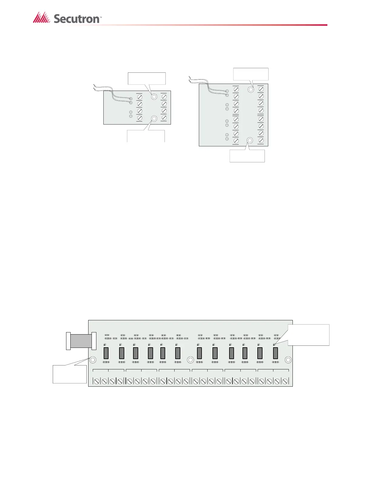
6.3 MR-2300-NC4/2 Output Class-A Converter Adder Module
Figure 11 MR-2300-NC4/2 Output Class-A Converter Adder Module
Indicating circuits must be wired from the MR-2300-NC4/2 to the main Fire Alarm board. For
example indicating circuit 1 positive (red wire) and negative (black wire) is wired from the
Class A converter module to the positive and negative terminals of Indicating circuit 1 on the
Main Fire Alarm board.
The actual indicating zone is wired from the SIGNAL OUT positive and negative to the
signaling devices and then wired back to the SIGNAL RET positive and negative.
6.4 Relay Adder Modules (Models MR-2312-R12 and MR-2306-R6)
6.4.1 MR-2312-R12 Twelve-Relay Adder Module
The ribbon cable from P1 of the MR-2312-R12 is connected to P6 on the Main Fire Alarm
Board. The jumpers located above each relay on the MR-2312-R12 are used to configure the
relays. The jumpers located below the relays are used to select either normally open contacts
or normally closed contacts.
Figure 12 MR-2312-R12 twelve relay adder module
P1: Cable from MR-2312-R12 Relay Adder Module connects to P6 on the Main Fire Alarm
Board.
+TUO
1GIS
-
+
T
UO 2GIS
-
+TE
R
1G
IS
-+
TER
2
G
IS
-
DER
KLB
DE
R
K
LB
mounting hole for
#6-32 screws
MR-2300-NC2
mounting hole for
#6-32 screws
+TUO
1GI
S
-
+TUO
2
GIS
-
+TER 1G
I
S -
+T
ER
2
GIS -
D
E
R
KLB
DER
K
LB
+TUO
3GIS -
+
TU
O
4GIS
-
+TER
3
GIS -
+
TE
R
4GIS -
DER
KL
B
DER KLB
mounting hole for
#6-32 screws
MR-2300-NC4
mounting hole for
#6-32 screws
NO/NC C
RELAY 1
NO/NC C
REL AY 2
NO/NC C
REL AY 3
NO/NC C
REL AY 4
C
REL AY 5
NO/NC C
RELAY 6
NO/NC C
RELAY 7
NO/NC C
REL AY 8
C
REL AY 9
NO/NC C
REL AY 10
NO/NC C
REL AY 11
NO/NC C
RELAY 12
NO/NC NO/NC
Three mounting
holes for #6-32
screws
INDIVIDUAL
GREEN RELAY
STATUS LEDs
Connect to P6 on the
main fire alarm board

 Loading...


