27
DIP Switch and Jumper Selections for Main Board and Adder Modules
6.4.2 Programming the relays
A typical relay circuit is shown below in Figure 13 with the jumper locations and descriptions.
Figure 13 MR-2312/06-R12/6 Relay programming
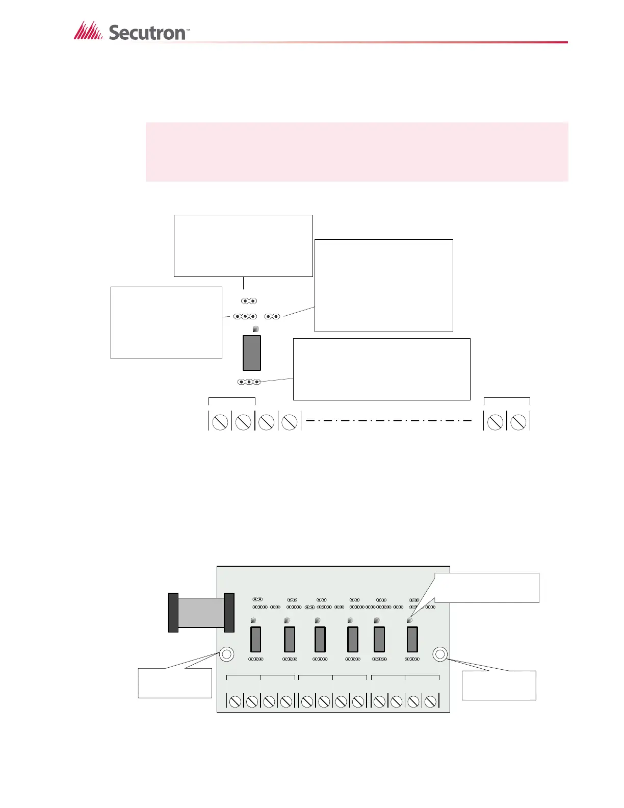
6.5 MR-2306-R6 Six Relay Adder Module
Cable from P1 of the MR-2306-R6 is connected to P6 on the Main Fire Alarm Board. The
jumpers located above each relay on the MR-2306-R6 are used to configure the relays. The
jumpers located below the relays are used to select either normally open contacts or normally
closed contacts.
Figure 14 MR-2306-R6 six relay adder module
Note: Relay programming should be done before installing the board.
NO NC
SA
Z1
1&2
NO/ NC C
RELAY 1
NC/NO CONNECTION
NC: terminal provides normally closed contacts
NO: terminal provides normally open contacts
Default: jumper is installed on normally open (NO)
Note: if the jumper is not installed on any selection
then the relay is not connected to the terminals
SUPV/ALARM SELECTION
S: Rel ay t ur ns ON when common
supervisory is active
A: Rel ay t ur ns ON when common
alarm is active
Default: No jumper installed,
connected on center pin only
ZONE JUMPER
installed: turns ON relay when the zone
(1) is active
removed: does not turn ON the relay when
zone (1) is active
Default: Jumper is installed
LOGICAL OR WITH ADJACENT ZONE
jumper installed: this relay 1 works in
conjunction with relay 2
jumper removed: relay 1 does not
operate with the adjacent relay 2
chaining example: if jumper is installed
on 1&2 and 2&3 then all the three relays
will be ON if any one of relays 1,2 and 3 is
active
Default: No jumper ins talled, connect ed
on one pin only
NO/ NC C
RELAY 12
RELAY
LED (G RE E N)
NO/ NC C
RELAY 1
NO/ NC C
RELAY 2
NO/ NC C
RELAY 3
NO/ NC C
RELAY 4
C
RELAY 5
NO/ NC C
RELAY 6
NO/ NC
mounting hole
for #6-32 screws
mounting hole
for #6-32 screws
INDIVIDUAL GREEN
RELAY STATUS LEDs
Connect to P6 on the
main fire alarm board

 Loading...


