91
15.0 Appendix D: Power Supply and
Battery Calculations (Selection
Guide)
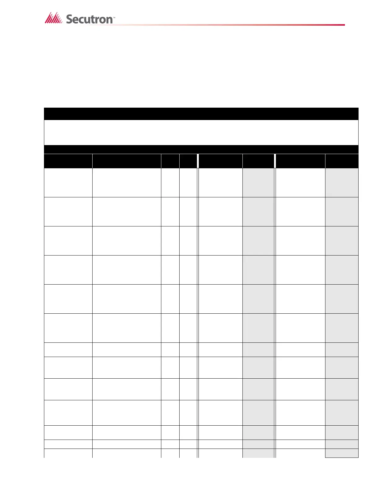
Use the form below to determine the required secondary power supply (batteries).
IMPORTANT NOTICE
The main AC branch circuit connection for Fire Alarm Control Panel must provide a dedicated continuous power
without provision of any disconnect devices. Use #12 AWG wire with 600-volt insulation and proper over-current
circuit protection that complies with the local codes. Refer to Appendix A for specifications.
Power Requirements (All Currents are in Amperes)
Model Number Description Qty Standby
Tot al
Standby
Alarm
Tot al
Alarm
MR-2312-
DDR
Fire Alarm Control
Panel, 12 Inp, 4Out
with UDACT
Using 3K9 resistors
X0.174
= 0.444 =
MR-2312-
DDR
Fire Alarm Control
Panel, 12 Inp, 4Out
with UDACT
Using active resistors
X0.104
= 0.394 =
MR-2306-
DDR
Fire Alarm Control
Panel, 6 Inp, 2 Out
with UDACT
Using 3K9 resistors
X0.142
= 0.312 =
MR-2306-
DDR
Fire Alarm Control
Panel, 6 Inp, 2 Out
with UDACT
Using active resistors
X0.112
= 0.282 =
MR-2306-DR
Fire Alarm Control
Panel, 6 Inp,2 Out
without UDACT
Using 3K9 resistors
X0.142
= 0.312 =
MR-2306-DR
Fire Alarm Control
Panel, 6 Inp, 2 Out
with UDACT
Using active resistors
X0.112
= 0.282 =
MR-2300-A
Det Class A Converter
Adder Module
X0.000
-0.000 0.000 -0.000
MR-2300-NC4
Sig Class A Converter
Adder Module--4
Circuits
X0.000
-0.000 0.000 -0.000
MR-2300-NC2
Sig Class A Converter
Adder Module--2
Circuits
X0.000
-0.000 0.000 -0.000
MR-2300-PR
Polarity Reversal and
City Tie Module
X0.050
=
0.300
(City Tie in
Use)
=
MR-2312-R12
12 Relay Adder
Module
X0.000
=0.160 =
MR-2306-R6 6 Relay Adder Module X 0.000
=0.080 =
MR-2312-S12 Smart Relay Module X 0.030
=0.140 =