24
DIP Switch and Jumper Selections for Main Board and Adder Modules
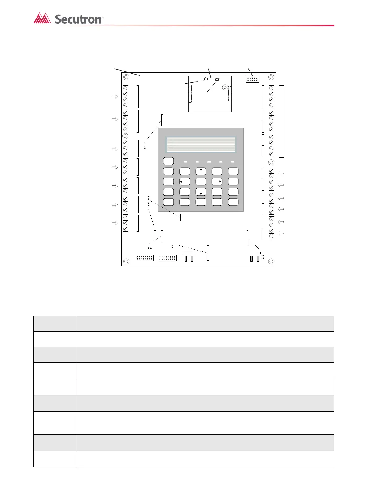
Figure 9 Main Fire Alarm Board DIP switch and jumper settings for MR-2300 LCD
Panels
Table 1 Connectors and Jumpers on the Main Fire Alarm Board
P5
Cable from P1 of the MR-2300-PR Polarity Reversal and City Tie Module connects here.
Otherwise not used.
P6
Cable from connector P1 of the MR-2312-R12 or MR-2306-R6 Relay Adder Module
connects here. Otherwise not used.
JW1
On the Main Fire Alarm Module, this jumper must be removed if a MR-2300-PR Polarity
Reversal and City Tie Module is installed.
JW2
Remove this jumper if a MR-2312-R12 or MR-2306-R6 Relay Adder Module is used.
JW3 Always open.
JW4
Normally open. Place jumper here and power down (AC and Batteries) then power back to
revert to default password. After reset remove the jumper. Leave normally open.
JW5
Normally open to BLOCK remote configuration via modem, PC with a UIMA converter
module or using the LCD and keys at the panel. Place jumper here to ALLOW any type of
configuration.
JW6 Not used, open (not available on MR-2306 LCD panels).
JW7 Not used, open.
S î +NC NOCNC NOCNC NOCNC NOC
CO M(+ )
CO M (î)
TRLTRB
RTRT
RTRT
RES CO RES CO
LINE1LINE2
JW2
JW 1
î +î +î +î +î +î +î +î +î +î +
DET 1DET 2DET 3DET 4DET 5DET 6
SIG 1SIG 2
TO PR-3 00 MO DULE TO RM-312 /RM-30 6 RELAY MO DULE
RS-485AUX. RELAYAL AR M R ELA Y
SUPERVISORY
RELAY
TROU BLE
RELAY
AUX
SUPPLY
4-WIRE
SUPPLY
UN FILTERED
RT I
PO RT
P1 P 2P3 P4
+ î
XT .CESYRETTAB
T
#
T
#
RS
a
A
A
S
upervisory Relay
Trouble Relay
Initiating zone 1 TO 6
CA fo yradnoces oTyrettaB oT
transformer
JW2 - ON- when
MR-2313-R12/
MR-2306-R6
not
connected
JW1 - ON- when
MR-2300-PR not connected
SYSTEM
RES E T
SIGN AL
SILENCE
FIRE
DRILL
BUZZER
SILENCE
LAMP
TEST
1
4
7
*
2
5
8
0
3
6
9
#
ENTER
MEN U
CAN CEL
IN FO
ABC DEF
GHI JKL MNO
PRS
TUV
WXY
QZ
A.C. ON ALARM SUPV TRBL CPU FAIL
SYSTEM NORMAL
18:01 MON 2003-04-05
AUX
SUPPLY
P5 P6
JW4
JW5
JW7
JW7
Always open
JW4 - Normally Open
JW5 - Normally Open
Signal Circuit -1
Signal Circuit-2
Auxiliary
Supply
4-wire Supply
Unfiltered 24V
supply
Connect to
Remote Trouble
Indicator
Main Fire Alarm Board
For PC programming use SUIMA
interface module not UL-864 or
ULC-S527 listed.
JW4 -Normally closed
JW5 -Normally open
JW4
JW5
Core Board
JW 3
JW3
Always open

 Loading...


