40
Turning on the Panel
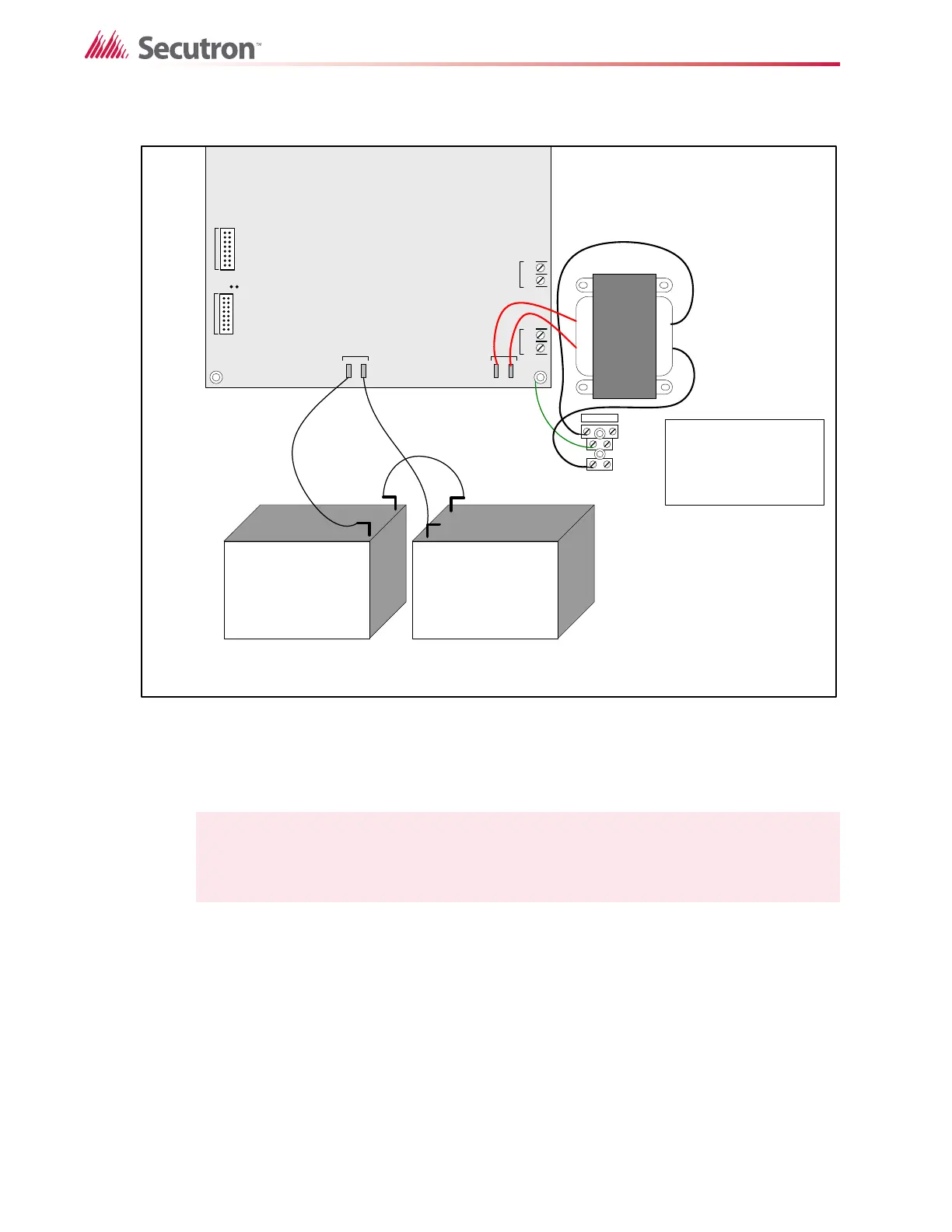
Figure 27 Power supply connection
All indicators should be off except for the green A.C. ON LED and the green TROUBLE LED in
the lower left corner of the main board.
4. Configure the Fire Alarm Control Panel as described in section 11 on page 53.
Note: Green LED I47 is illuminated when the system is normal. This LED indicates that
the trouble relay is in normal standby condition.
JW1
-+-+
SIG 3SIG 4
TO PR- 300 MO DULE
TO RM-312/RM-306 RELAY
MODU LE
P1 P2P3 P4
+
_
BATTERY
SEC. TX
L
G
N
white
black
green
blk
blk
red
red
red
red
blk
+
+
_
_
Connect AC power here:
white wire to L
green wire to G
black wire to N
Battery Battery
NOTE: TO PREVENT SPARKING, CONNECT BATTERIES AFTER THE
SYSTEM MAIN A.C. POWER IS TURNED ON