28
DIP Switch and Jumper Selections for Main Board and Adder Modules
P1: Cable from MR-2306-R6 Relay Adder Module connects to P6 on the Main Fire Alarm
Board.
6.5.1 Programming the relays
See explanation in Figure 13.
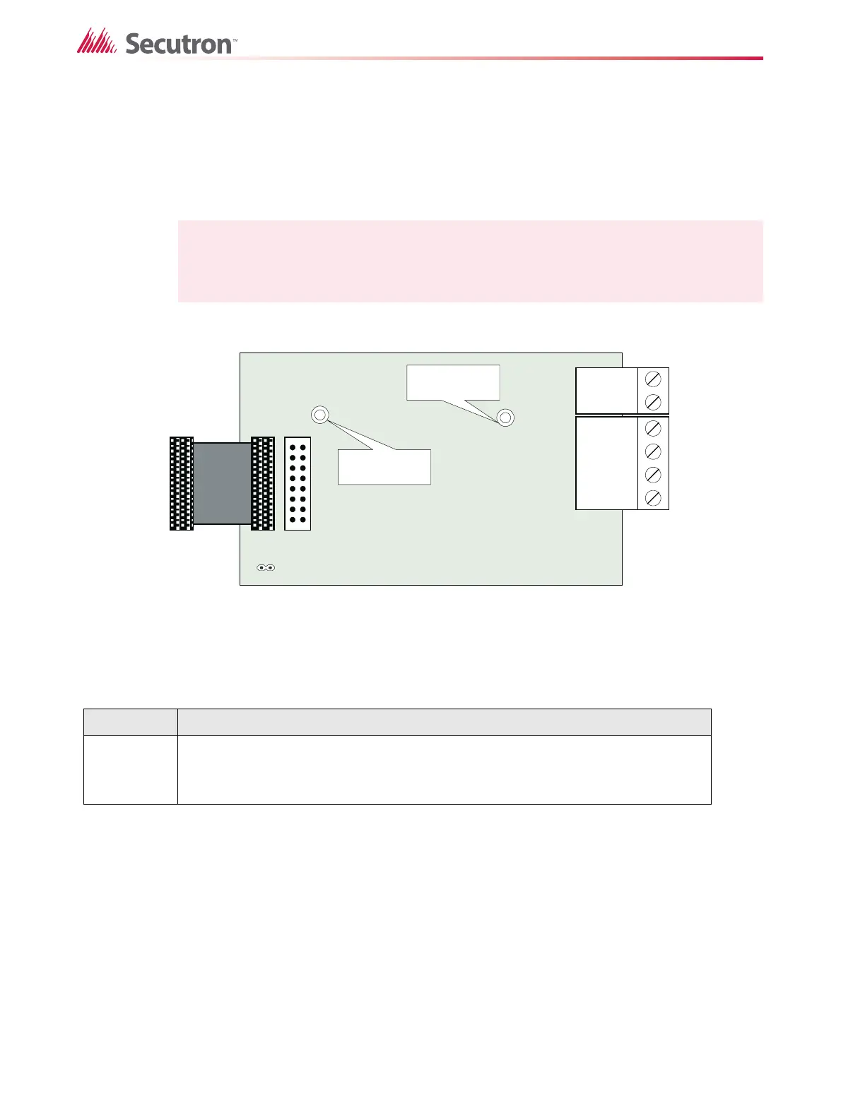
6.6 Polarity Reversal and City Tie Module (Model MR-2300-PR)
Figure 15 Polarity reversal and city tie module
The following hardware configuration must be performed before installing the MR-2300-PR
Table 3 MR-2300-PR jumper settings
The Alarm Transmit signal to the MR-2300-PR can be programmed to turn OFF when signal
silence is active. This allows the City Tie Box to be manually reset. On subsequent alarms the
silenceable signals will resound and the City Tie Box will be retriggered. See section 11 on
page 53 for more information.
The Trouble Transmit signal to the MR-2300-PR can be programmed to delay AC power fail
for 0 to 3 hours if this is the only system trouble. See section 11 on page 53.
Note: Relay programming should be done before installing the board.
P1 Cable connects to P3 on the Main Fire Alarm Board
P2 & JW4 Not used with MR-2300 Fire Alarm Panel. Jumper JW4 remains on board.
POLARITY
REVERSAL
ALARM
POLARITY
REVERSAL
SUPV
CITY
TIE
+ | - + | - + | -
JW4
P1 P2
Mounting hole for
#6-32 screws
Mounting hole for
#6-32 screws

 Loading...


