two. 8-bit even number between 2 to 250
First register – high byte
First register – low byte
Last register – high byte
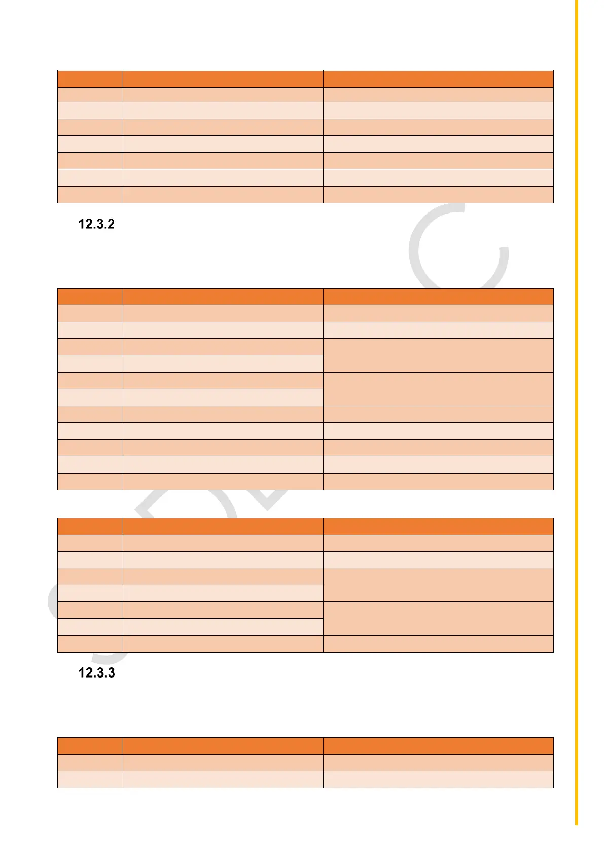
Function 16 (0x10): Write Holding Registers
This function is used to issue certain commands to the controller. The command-response pattern is as
shown in Table 34 and Table 35.
Table 34: Command from MODBUS master for Function 16
As configured in genset controller
First register address – high byte
16-bit register address, register address map
is described in Table 38
First register address – low byte
Number of registers to write – high byte
Number of registers to write must be between
1 to 255
Number of registers to write – low byte
Number of data bytes to follow (n)
Table 35: Normal response from genset controller slave for Function 16
As configured in genset controller
First register address – high byte
16-bit register address, register address map
is described in Table 38
First register address – low byte
Number of registers written – high byte
Number of registers that have been written
Number of registers written – low byte
Function 3 (0x03): Read Holding Registers
This function is used to read holding registers that is the commands that have been issued to the
controller. The command-response pattern is as shown in Table 36 and Table 37.
Table 36: Command from MODBUS master for Function 3
As configured in genset controller