SEL-487B Data Sheet Schweitzer Engineering Laboratories, Inc.
10
because the relay dynamically computes the station
connection replica by using the patented zone-selection
algorithm.
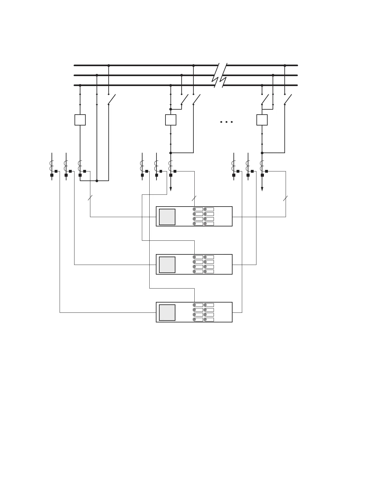
Figure 18 shows a busbar layout consisting of two main
busbars and a transfer bus, one busbar coupler, and 20
terminals.
Figure 18 Three SEL-487B Relays Protect Two Main Busbars and a Transfer Busbar, Bus Coupler, and 20 Terminals
Optimize your SEL-487B by protecting both HV and LV
busbars with three relays. Figure 19 shows two HV
busbars and two LV busbars. Use of four zones for the
four busbars (two HV and two LV) still leaves two zones
available in each relay. We can configure independent
check zones for HV and LV bus protection supervision.
Bus 1
Bus 2
Transfer Bus
1
52
400/5
1
52
800/5
FDR_1
1
52
4000/5
FDR_20
SEL-487B
SEL-487B
SEL-487B
(C-Phase)
(B-Phase)
(A-Phase)
 Loading...


