Schweitzer Engineering Laboratories, Inc. SEL-487E Data Sheet
13
Circuit Breaker Operations From the
Front Panel
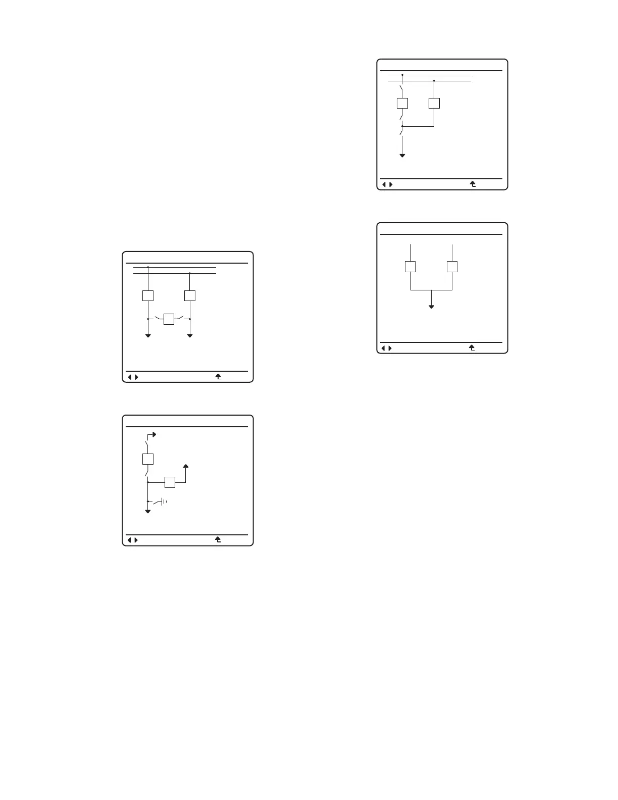
Figure 15–Figure 18 are examples of some of the select-
able one-line diagrams in the SEL-487E. Select the one-
line diagram from the Bay settings. Additional settings
for defining labels and analog quantities are also found in
the Bay settings. One-line diagrams are composed of the
following:
➤ Bay names and bay labels
➤ Busbar and busbar labels
➤ Breaker and breaker labels
➤ Disconnect switches and disconnect switch labels
➤ Analog display points
Figure 19 shows the breaker control screens available
when the ENT pushbutton is pressed with the circuit
breaker highlighted as shown in Figure 19(a).
Figure 15 Breaker-and-a-Half
Figure 16 Ring Bus With Ground Switch
BAYNAME
BK2
BK1
SW1
SW2
BK3
BAYLAB2BAYLAB1
BUSNAM1
BUSNAM2
ESCNAVIG
BAYNAME
6 ANALOGS
I:99999.9 A
V:99999.9 KV
P:99999.9 MW
Q:99999.9 MV
F:99.9 HZ
BAYLAB1
SW2
SW3
BK1
BK2
SW1
BAYLAB2
ESCNAVIG
Figure 17 Double Bus/Double Breaker
Figure 18 Source Transfer Bus
BAYNAME
6 ANALOGS
I:99999.9 A
V:99999.9 KV
P:99999.9 MW
Q:99999.9 MV
F:99.9 HZ
BUSNAM1
SW2
SW3
BK1
BK2
SW1
BUSNAM2
ESCNAVIG
BAYNAME
BUSNAM1
BK1
BK2
BUSNAM2
BAYLAB1
I:99999.9 A
V:99999.9 KV
P:99999.9 MW
I:99999.9 A
V:99999.9 KV
P:99999.9 MW
ESCNAVIG



 To Next Page