90 Description of machine operation
5.2)
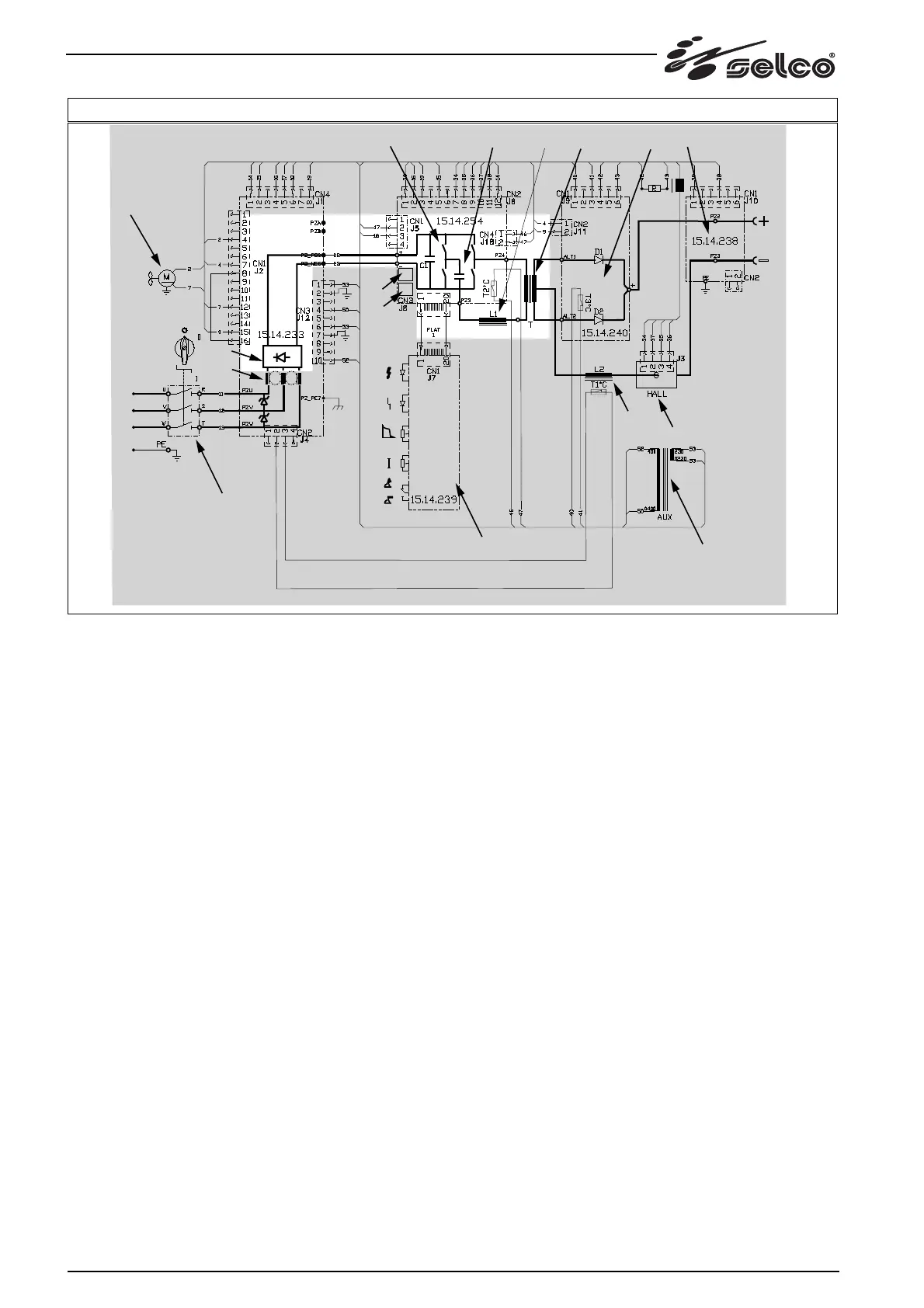
rectifier bridge (c) - power inverter with overtemperature
detection device (d) - resonant circuit (inductive-capacitive
circuit) (e) - power transformer (f)
(see fig. 5-6)
The three-phase power supply voltage is applied to the rectifier
bridge (c), the output of which is connected to the power inverter
(d) via cables no.22(+) and no.23(-).
The inverter has a bridge type structure with four power IGBTs
(one on each branch) welded directly to board 15.14.254 and
fixed to the aluminium radiator by means of screws.
The resonant circuit (inductive-capacitive circuit) at the inverter
output terminals and the presence of an auxiliary circuit on
board 15.14.254 permit operation at high (variable) frequency.
The auxiliary circuit consists of two IGBTs and two power
diodes fixed on the aluminium radiator by means of a profiled
plastic bar, but electrically insulated from the radiator by a strip
of insulating tape with low thermal resistance.
The IGBT switch-on control circuit is located on board
15.14.254.
The radiator is cooled by the air flow generated by the fan (k)
powered at 230Vac. This voltage is insulated from the mains by
means of the auxiliary transformer (l) and protected by a fuse on
board 15.14.233. The air flows from the rear grille (air inlet) of the
machine towards the front grille (air outlet). The inverter is
protected against overloads or blocking of the ventilation air flow
by a radiator temperature detection device; this device sends a
signal to the control logic which then locks the inverter and signals
the fault to the front panel.
The power transformer (f), positioned in series with the inducti-
ve-capacitive load, transfers the power to the output circuits
which are therefore electrically insulated from the power supply
network.