14 Description of operation of the power sources and technical dates
7.0 ASSEMBLING THE EQUIPMENT
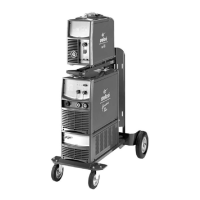
7.0.1 Assembling the movable trolley
For the assembly of the generator trolley GT23, see SPARE
PARTS TABLES.
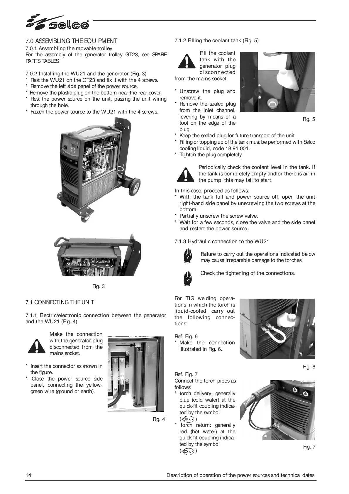
7.0.2 Installing the WU21 and the generator (Fig. 3)
* Rest the WU21 on the GT23 and fix it with the 4 screws.
* Remove the left side panel of the power source.
* Remove the plastic plug on the bottom near the rear cover.
* Rest the power source on the unit, passing the unit wiring
through the hole.
* Fasten the power source to the WU21 with the 4 screws.
7.1 CONNECTING THE UNIT
7.1.1 Electric/electronic connection between the generator
and the WU21 (Fig. 4)
Make the connection
with the generator plug
disconnected from the
mains socket.
* Insert the connector as shown in
the figure.
* Close the power source side
panel, connecting the yellow-
green wire (ground or earth).
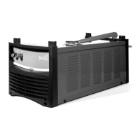
7.1.2 Filling the coolant tank (Fig. 5)
Fill the coolant
tank with the
generator plug
di sconn ect ed
from the mains socket.
* Unscrew the plug and
remove it.
* Remove the sealed plug
from the inlet channel,
levering by means of a
tool on the edge of the
plug.
* Keep the sealed plug for future transport of the unit.
* Filling or topping up of the tank must be performed with Selco
cooling liquid, code 18.91.001.
* Tighten the plug completely.
Periodically check the coolant level in the tank. If
the tank is completely empty andlor there is air in
the pump, this may fail to start.
In this case, proceed as follows:
* With the tank full and power source off, open the unit
right-hand side panel by unscrewing the two screws at the
bottom.
* Partially unscrew the screw valve.
* Wait for a few seconds, close the valve and the side panel
and restart the power source.
7.1.3 Hydraulic connection to the WU21
Failure to carry out the operations indicated below
may cause irreparable damage to the torches.
Check the tightening of the connections.
For TIG welding opera-
tions in which the torch is
liquid-cooled, carry out
the following connec-
tions:
Ref. Fig. 6
* Make the connection
illustrated in Fig. 6.
Ref. Fig. 7
Connect the torch pipes as
follows:
* torch delivery: generally
blue (cold water) at the
quick-fit coupling indica-
ted by the symbol
( )
* torch return: generally
red (hot water) at the
quick-fit coupling indica-
ted by the symbol
( )
Fig. 3
Fig. 4
Fig. 5
Fig. 6
Fig. 7