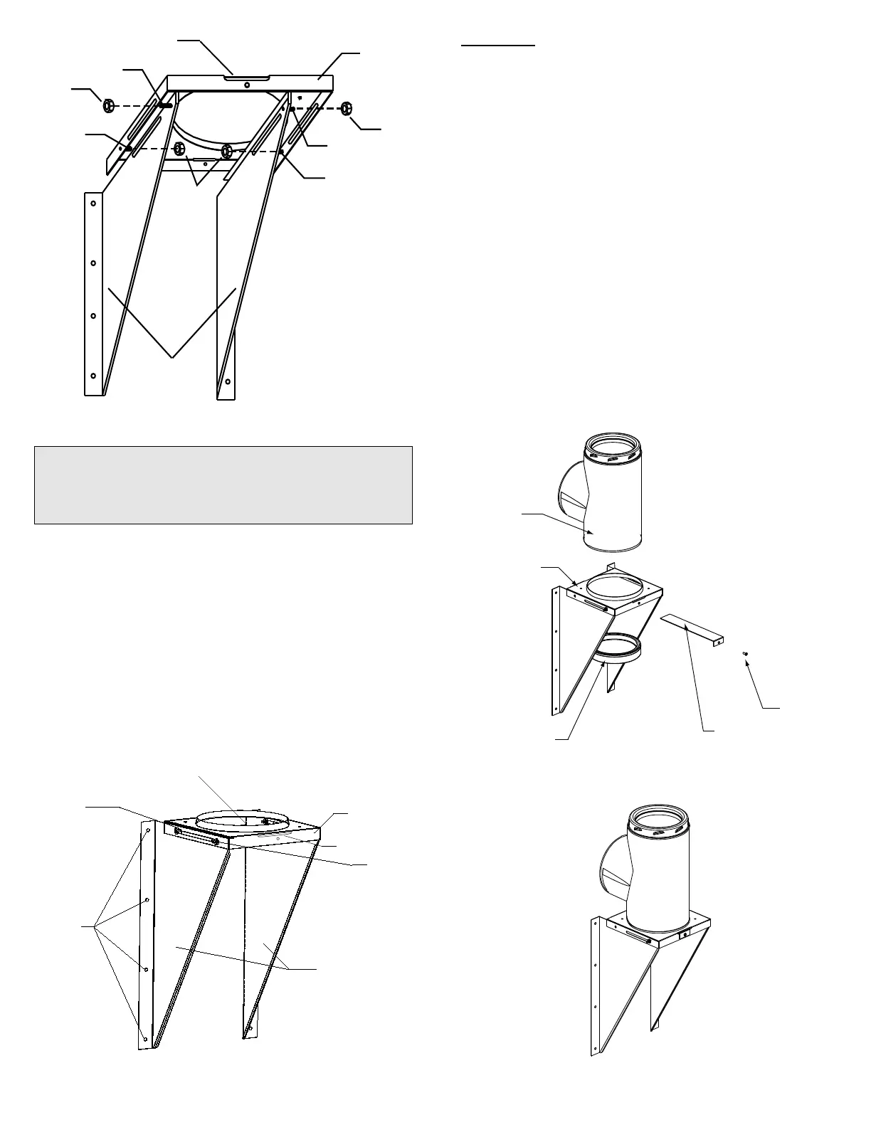
11
Support Side
Brackets
Support Bracket
Threaded Stud
Nut
Support
Plate
Nuts
Nut
Support Bracket
Threaded Stud
Support
Plate
Threaded
Stud
(toward
wall)
FIGURE 14
UNDERSIDE VIEW OF THREADED STUDS AND NUTS
Slot for Tee Cap Bracket
Support Plate
Threaded
Stud (toward
wall)
NOTE: THE CHIMNEY LENGTH MUST EXTEND AT LEAST
3” THROUGH THE WALL INTO THE LIVING SPACE WHERE
THE STOVE PIPE CONNECTOR WILL BE
ATTACHED TO THE CHIMNEY BRANCH.
9. Prior to securing ensure that the Insulated Tee assembly is plumb
and level and sitting flush on the Support Plate. Secure to the wall
through the pre-punched holes located on each side of the Wall
Stud and Nut
located to front
of Support
Bracket
Support
Brackets
Threaded
Stud
and Nut
located at
rear of
Support Plate
Pre-
Punched
Holes of
Support
Bracket
Flange Up
FIGURE 15
FRONT VIEW OF WALL SUPPORT ASSEMBLY
Support Plate
Slot for Tee Cap
Bracket
Insulated
Tee
Support Plate
METHOD B
11. Position the Wall Support so that the Insulated Tee will be
centered inside the Wall Thimble. Ensure that the Wall Support is
level, and secure to the wall through the pre-punched holes located
on the sides of each of the support brackets using (8) #14 x 1-1/2"
hex head lag screws or #10 x 1-1/2" wood screws. You can drill 5/32"
pilot holes for the lag screws. Make sure they go into solid bracing
as per the requirements in Table 3 Section B and Figure 13 (B) below
the prepared Wall Thimble opening. For concrete block or poured
foundation use suitable fasteners.
12. Place the Insulated Tee on the support Plate ensuring that the
male coupler of the Tee is facing up and the flange on the top of the
Support Plate slides into the female coupler (see Figures 16 & 17).
Insulated Tee Cap
Tee Cap
Bracket
Securing
Screw
FIGURE 17 - Assembled Wall Support
with Tee Cap Secured in Place
FIGURE 16 - Explosion View - Wall Support, Insulated
Tee and Tee Cap, Tee Cap Bracket and securing
Screw.
10. Position the Support Plate to the desired distance from the wall
as per the limits shown in Table 2 and Figure 11. Tighten the 4 nuts
onto the threaded studs. Proceed to Step 14.
Support Brackets using (8) #14 x 1-1/2" hex head lag screws or #10
x 2" wood screws. Make sure they go into solid bracing as per the
requirements in Table 3 Section B and Figure 13 (B), below the
prepared Wall Thimble opening. You can drill 5/32" pilot holes. For
concrete block or poured foundation use suitable fasteners.
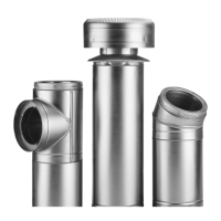
13. From inside the building, slide an appropriate Insulated Chimney
Length such as a one foot section (or longer if required - not to exceed
24 inches) through the Wall Thimble to the horizontal branch of the
Insulated Tee. Lock securely into the Tee branch by twisting
clockwise. A Locking Band must then be installed to secure the
connection. Make sure the nut and bolt are facing down to prevent
any water from collecting in the Locking Band. The Tee Branch
extension must protrude a minimum of 3" into the room.