16
10’
MAX
2/3 H
Masonry
Adapter Plate
Anchor Screws
FIGURE 36
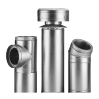
Masonry Adapter
Installation
Chimney Section(s)
Rain Cap
Masonry Adapter Flashing
Storm Collar
MASONRY ADAPTER KIT (MAK)
The Masonry Adapter Kit is intended for use in replacing part of a
damaged existing masonry chimney with model JM/ALT chimney.
It could also be used for adapting "listed" factory-built fireplaces to
model JM/ALT chimney. Follow the installation instructions sup-
plied with the factory-built fireplace.
Masonry Chimney Outline
Masonry Adaptor
Flashing
FIGURE 37
Masonry Adapter
Flashing Installation
Notched Corner(s)
In order to adapt an existing masonry chimney to the model JM/ALT
chimney, the following parts are required:
- Masonry Adapter Kit (MAK): The kit includes a Masonry
Adaptor Plate, Masonry Adapter Flashing and Storm Collar
- Suitable lengths of chimney
- Rain Cap: Standard or Deluxe model.
Depending on the installation, other parts that may be required are:
- Wall Band(s)
- Roof Flashing Assembly
- Roof Guy Kit
- Finishing Plate
H. Attach the other end of each telescoping leg assembly to an Angle Bracket
using one (1) 1/4-20 X 1” bolt and nut (see Figure 34).
Elevator Bolt
Angled end of Leg
Flat Washer
Flanged Nut
Elevator
Bolt
Angled end of Leg
Flat Washer
Flanged Nut
Figure 33
Assembly of Telescoping
Legs to Support Band
Flat Washer Flat Washer
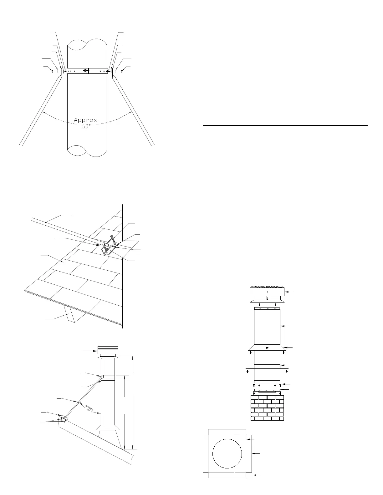
J. Make sure the chimney is level and plumb. Check all required dimensions
and angles, adjust if necessary. For added security, lock legs in place by
using 1/8” x 1/2” stainless steel self tapping screw (supplied) through
the pilot holes found near the hose clamps (Figure 32).
K. The two telescoping legs should form an angle of about 60° to give
support to the chimney in all directions. The angle of the telescoping
legs should be approximately 45° from vertical when fastened to the
roof (see Figures 33 & 35).
Flanged Nut
Smaller Diameter Leg
Roof Shingles
Rafter or framing
structure
1” Bolt
Angle Bracket
2” Lag Screw
Figure 34
Securing
Angle Bracket
2” Lag Screw
I. Determine the location of the two Angle Brackets on the roof structure.
Ensure the fasteners are into rafters or framing and not just roof
sheathing. Secure the Angle Brackets to the roof structure using two
(2) 1/4 X 2” lag screws per brackets (see Figure 34). Apply a thin layer
of caulking under the angle bracket (before securing in place) as well as
over the lag screw heads.
NOTE: Do periodic inspections of all fasteners including the hose clamps
as high winds can cause the chimney system above the roof to vibrate and
in time loosen some of the fasteners.
Rain Cap
Support Band
Locking Band
Angle Bracket
2” Lag screws
Hose Clamp
Placement of Universal
Roof Brace Kit
Figure 35