6
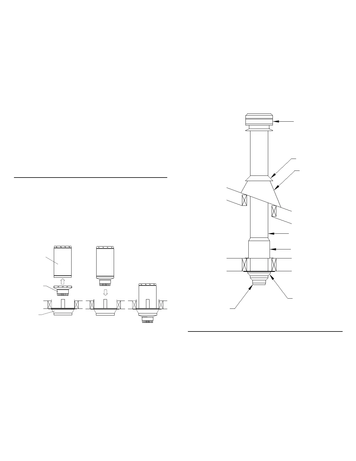
ATTIC INSULATION SHIELD (AIS)
Single Story Installation
Unenclosed
Attic Space
Roof Joist
Rain Cap
Storm Collar
Ventilated Flashing
Attic Insulation Shield
Decorator Ceiling Support
Chimney Section
Stove Pipe Adapter
Ceiling Joist
(Framed all 4 sides)
FIGURE 5
Install additional chimney sections and lock together by turning
clockwise until the two sections lock together snugly. Even though
Locking Bands are optional, it is always recommended to install a
Locking Band to secure the two chimney sections. Continue adding
chimney lengths until a height of about 2 ft. below the next ceiling level
is achieved.
NOTE: The Decorator Ceiling Support cannot be used when the
chimney terminates in a room with a suspended ceiling. When false
ceiling are encountered, use a Cathedral Ceiling Support to extend
into the room below the finished ceiling. The floor/ceiling joist must
be framed on all 4 sides. The box must extend a minimum of 1" below
the suspended ceiling. The chimney length is to protrude a minimum
of 3" below the support and the trim angles must be installed.
An Attic Insulation Shield must be installed where a chimney passes
from a lower living space into an upper living space or into an attic
space. It is designed to keep insulation materials from coming into
contact with the chimney and will protect up to a 10" (250 mm)
thickness of insulation. The height of the Attic Insulation Shield is
to meet the insulation level requirement of the National Building
Code. Where height restrictions will not permit the use of the Attic
Insulation Shield, it is permissible to construct an enclosure with the
required air space clearance to the outer pipe all the way to the
underside of the roof deck. All chimney enclosures must maintain the
required minimum air space clearance of 2" (50mm) to the chimney.
When enclosing the chimney below the roof line, a Rafter Radiation
Shield (RRS) must be installed at the roof level (see Figures 6 and 21).
For a proper installation, the opening must be fully framed at
2 inches of clearance to the ouside casing of the chimney with
framing material of the same dimension as the ceiling or floor joist
as per the Framing Dimensions in Table 1.
The Decorator Ceiling Support will support up to 40 ft. (13 m) of
chimney sections, all of which must be installed above the support.
Figures 5 & 6 show the 2 most common types of Decorator Ceiling
Support Installation. Frame (on all 4 sides) a level square opening
with the inside dimensions of 14-3/8" (365mm) square. Remember
to cut a round hole on the finishing (gyprock) side.
Slide the Trim Ring (Finishing Plate) onto the Decorator Ceiling
Support and position the assembly into the framed opening from
below. Ensure that the Finishing Plate is flush with the underside of
the ceiling and the assembly is level and plumb. Secure in place with
3 x 6d (2”) nails or #8 x 1-1/2" wood screws through each of the 4
straps.
- Suitable Lengths of Chimney : The chimney diameter should be sized
to suit the appliance.
- 15
o
or 30
o
Chimney Elbow Kit : To avoid cutting of joists and clear other
obstructions. Kit includes: 2 Elbows, 1 Offset Support and 4 Locking
Bands.
- Rain Cap: To prevent rain and/or debris from entering in the chimney.
Standard or Deluxe model.
The crimped end (stub) of the Stove Pipe Adapter is intended to fit
inside of the flue pipe from a solid fuel appliance, thus preventing
condensate drips at the chimney connection.
Install inter-connecting flue pipe following the appliance
manufacturer’s installation instructions and appropriate building
code requirements and the Installation Code B-365, keeping in mind
that the flue pipe run should be as short and straight as practicable.
Generally, for a wood burning appliance installation, an 18” minimum
clearance to combustibles must be maintained for a single wall flue
pipe. The exception to this is a double wall stove pipe, such as
Selkirk's Model DSP which can be installed at reduced clearances to
combustibles. See separate installation instructions for more details.
Stove Pipe
Adapter (ASE)
Decorator
Ceiling
Support
Chimney
Length
STOVE PIPE ADAPTER (ASE)
STOVE PIPE ADAPTER (ASE)
The Stove Pipe Adapter (ASE) is installed by twist-locking it into the
bottom end (female end) of the first Chimney Section that enters the
Ceiling Support. Do not install an elbow in the Ceiling Support. Make
sure that the male coupler of the insulated Chimney Length is pointing
upwards as indicated by the arrow on the chimney label. Lower the
assembly down into the Decorator Ceiling Support ensuring that the
Stove Pipe Adapter sleeve is protruding through the support and into
the living space (see Figure 4).
FIGURE 4
 Loading...