1.2. Key Requirements / Wiring Diagram
Key Requirements
1. Each EV charging station shall be on a dedicated electrical circuit.
2. Each station shall be protected with a 40 Amp 2-pole common trip circuit breaker (non-GFCI type).
3. Each station is designed to draw a maximum of 30Amps.
4. Each station can operate on either a 240V or 208V circuit.
5. Each station requires three electrical supply wires (two hot, one ground, no neutral).
6. All data communication is wireless, so there is no data cabling to install, but cellular communication is
required.
Wiring Diagram
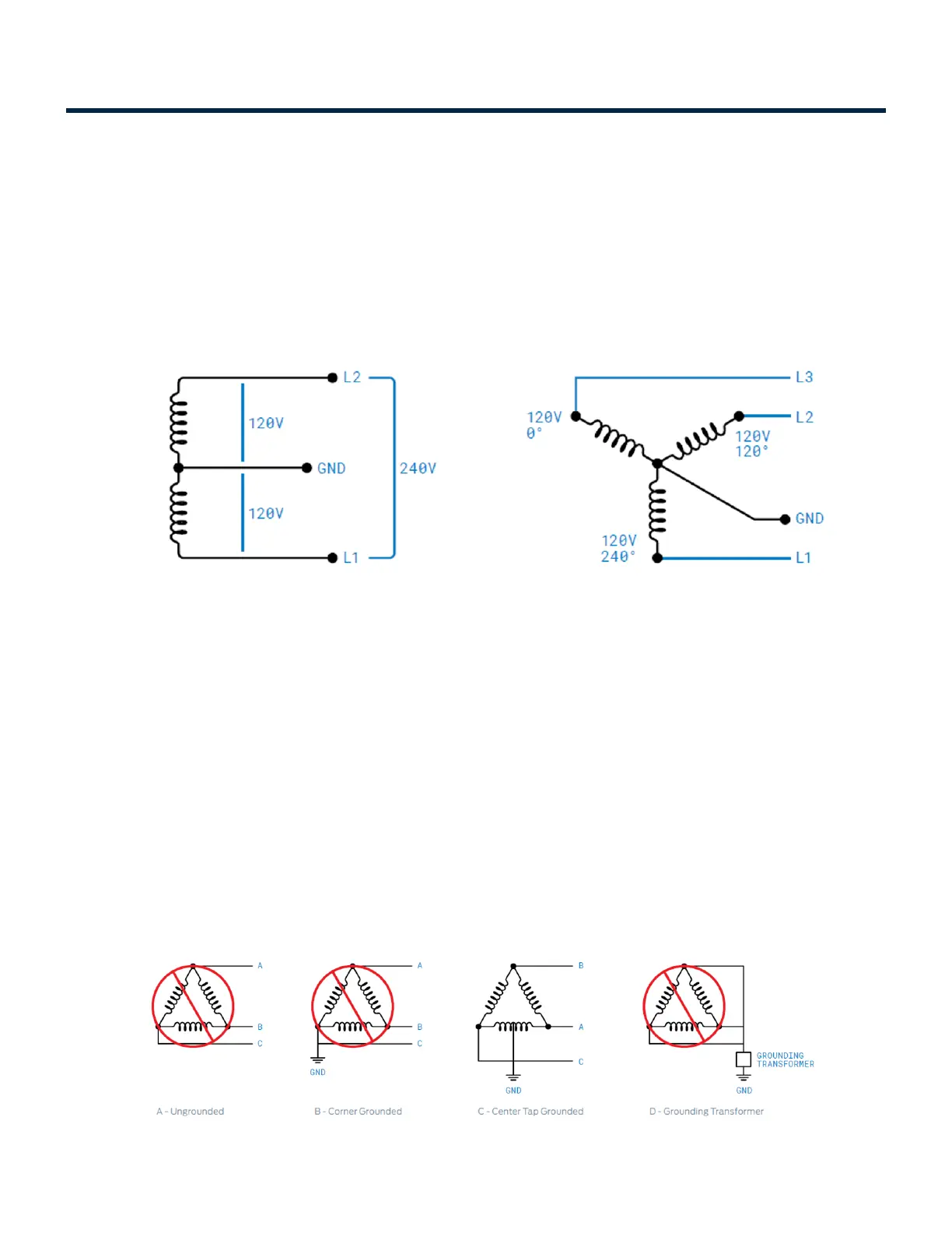
Connect SemaConnect stations to any one of the power sources as shown:
1. 208 VAC three phase , Delta system, Center tap grounded (use only two phases)
2. 208 VAC three phase, Wye system (use only two phases)
3. 240 VAC single phase
In a delta system, connect the SemaConnect station only to a center-tapped grounded transformer only as
shown below. Connect the station to the side where ground is bonded (in figure C line A and C). This allows
voltages to remain constant regardless of other loads that may be using the lines. Please do not connect to
other type of power sources shown below.
Installation Manuals Series 6 EV Charging Station - 1
Copyright ©2021 SemaConnect, Inc. All rights reserved. Page 3 of 25