Product overview
8 | Flex 5000
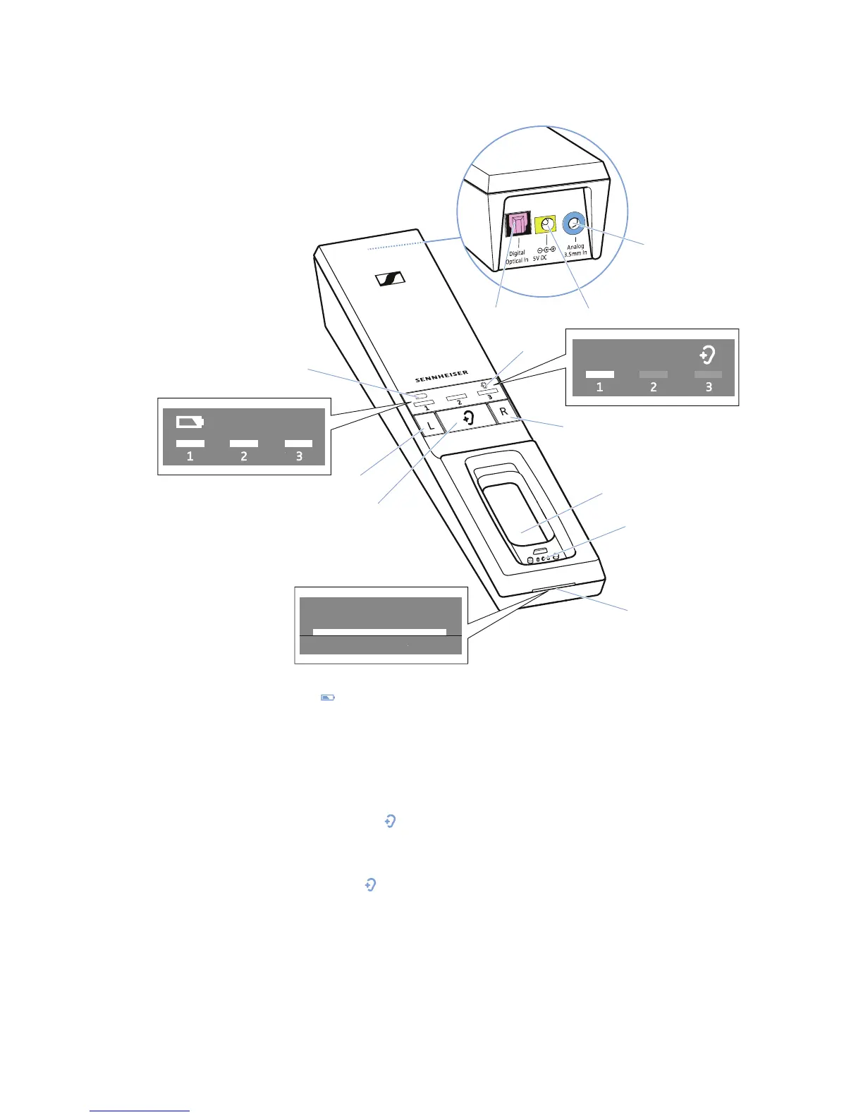
Overview of the TR 5000 transmitter
0
9
8
1A
1
Battery
LED ,
indicating the charging process/
remaining operating time of the
receiver (see page 16 and 17)
2 Balance buttons
for right ear
R and left ear L
3
Hearing profile
button
for selecting the hearing profiles
(see page 23)
4
Hearing profile
LED ,
indicating the activated hearing
profile (see page 23)
5 Charging compartment for receiver
6 Charging contacts for receiver with
holding magnets
7
Transmitter status
LED
(see page9)
8 Digital Optical In audio input (marked
pink) for connecting a digital audio
source (optical)
9 5V DC 1A socket (marked yellow) for
connecting the power supply unit
0 Analog 3.5 mm In audio input
(marked blue) for connecting an
analog audio source
(3.5 mm jack socket)