SENNHEISER ELECTRONIC GMBH & CO. KG
COMPONENT MAINTENANCE MANUAL
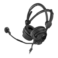
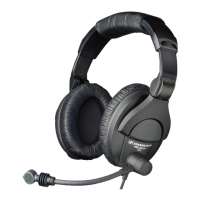
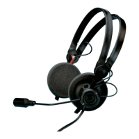
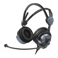
HMEC 26 SERIES
Page 1009
Feb 10/10
23-41-48
For battery-powered Headsets (-BV-K, -BV-CP, -B-CP, -B-K):
K. Test of the jack sockets of the operation control
NOTE:
THIS PROCEDURE IS ONLY APPLICABLE TO HEADSETS WITH CABLES -BV-K AND -BV-KP.
ACTION RESULT
(1) Only applicable to -BV-KP, -BV-K, -B-K,
-B-KP, -BV-CP, -B-CP. Connect power
supply (1, Table 1001) at battery
contacts directly with the positive and
negative line.
(a) Supply 3 V DC to the battery
contacts.
The LED comes on yellow:
The battery capacity is sufficient.
(b) Supply 2.2 V DC to the battery
contacts.
The LED comes on red:
The battery has the lowest working capacity.
(c) Supply 1.9 V DC to the battery
contacts.
The LED stays off:
The battery capacity is flat.
(2) Remove the test cable.
ACTION RESULT
(1) Connect the test cable of the power
supply (1,Table 1001) to the related
NoiseGard
™ pins of the Cable (Ref. Fig.
1004).
Supply a voltage of between 12 V DC
to 35 V DC.
As an alternative, put fully charged
batteries in the control unit.
(2) Set the NoiseGard™ switch to ON.
(3) Put on the headset.
Be sure that the mono/stereo switch is
in stereo mode.
(4) Supply an external stereo audio signal to
the 3.5 mm jack socket of the headset
control unit.
You can hear the external stereo audio signal in
the left and right capsule.
(5) Use a mobile-phone adapter-cable to
connect your mobile phone to the
2.5 mm jack socket of the control unit.
(6) Connect the Cable to the intercom
(5, Table 1001).
(7) Set up a phone connection to the mobile
phone and receive the call.
You can hear the caller’s voice in the left and
right capsule and you can speak to the
caller.
Oct 30/08