Page 16 UltraWave Product Guide
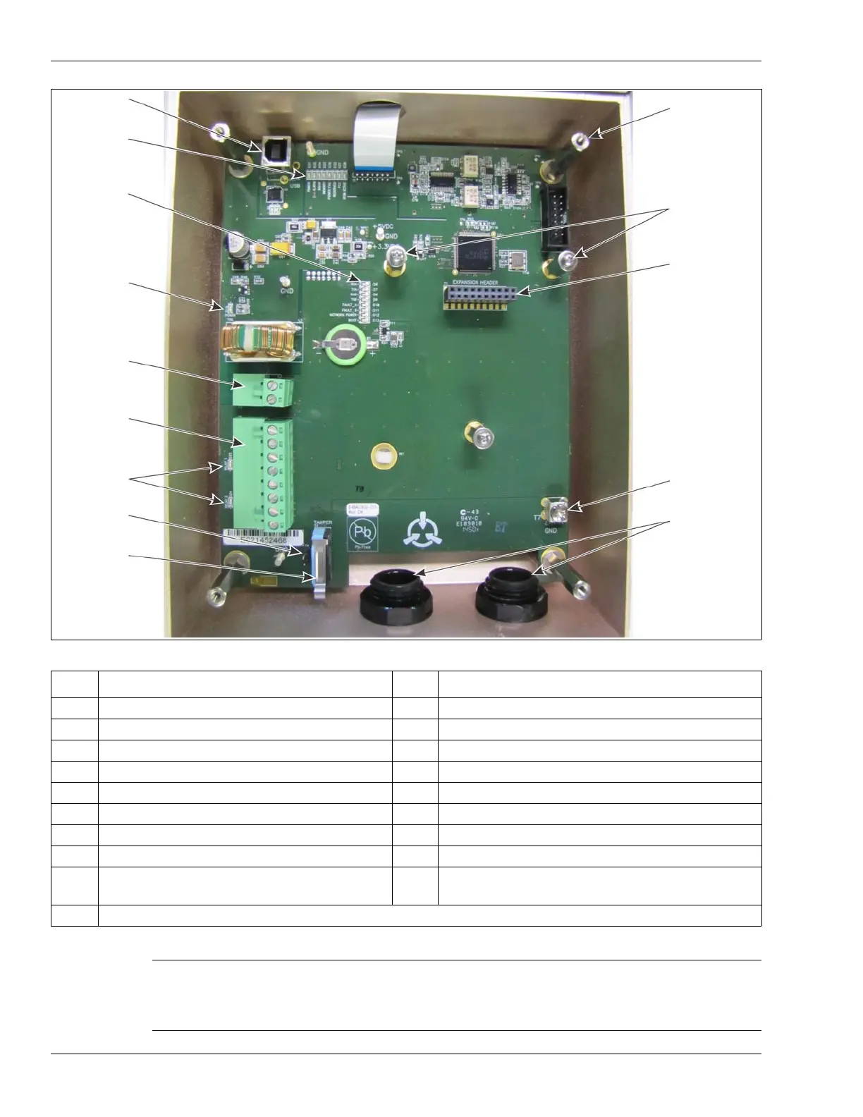
Figure 11 UltraWave receiver unit
LED # Description LED # Description
D37 POWER LED ON = DC input Power ON D6 RXA LED ON = receiving A-side network comm
D35 ALARM LED ON = microwave sensor alarm D7 TXA LED ON = transmitting A-side network comm
D34 DOOR LED ON = enclosure tamper condition D8 RXB LED ON = receiving B-side network comm
D33 MEMORY LED ON = internal memory fault D9 TXB LED ON = transmitting B-side network comm
D36 POWER FAIL LED ON = power rail fault D10 FAULT A LED ON = A-side communication fault
D32 RESERVED D11 FAULT B LED ON = B-side communication fault
D31 RESERVED D12 NETWORK POWER LED ON = NIC power ON
D30 UCM ACTIVE LED ON = UCM connected D13 BOOT LED ON = NIC initialization failure
D24 ALARM LED ON = output 2 activated (sensor
alarm by default/configurable in Local control)
D16 POWER LED ON = input power fault
D25 SUPERVISION LED ON = output 1 activated (supervision alarm by default/configurable in Local control)
Table 5 UltraWave diagnostic activity LEDs
Note LEDs D6 to D13 also function as a received signal strength
indicator (RSSI) to aid in the final alignment of the UltraWave
system. The tamper switch must be pressed or the shunt must
be installed on T4 to enable the RSSI LED function.
USB port
NIC mounting
T1 expansion
power fault
T3 power
T6 input
relay activity
T4 tamper
S1 tamper
T7 PCB earth
21.5 mm cable
fitted with
D37 - D30
D6 - D13
received
entry ports
compression
glands
ground
connection
switch
bypass
LEDs
header
(for NIC)
output
connections
connection
LED D16
diagnostic &
diagnostic
connect UCM
hardware (X 2)
cover
mounting
standoffs (X 4)
LEDs
signal
strength
indicator
(DO NOT tighten
LEDs
standoffs)